My US Congressman is: Mike Turner [OH-10] ; Sherrod Brown and Rob Portman are my US Senators. I hope my videos – helped elect US President Biden. Video. I can make more videos – if needed.
Introduction ... Each person who wants to market in the U.S., a Class I, II, and III device intended for human use, for which a Premarket Approval application (PMA) is not required, must submit a 510(k) to FDA unless the device is exempt from 510(k) requirements of the Federal Food, Drug, and Cosmetic Act (the FD&C Act) and does not exceed the limitations of exemptions in .9 of the device classification regulation chapters (e.g., 21 CFR 862.9, 21 CFR 864.9). ... There is no 510(k) form; however, 21 CFR 807 Subpart E (LINK) describes requirements for a 510(k) submission. Before marketing a device, each submitter must receive an order, in the form of a letter, from FDA which finds the device to be substantially equivalent (SE) and states that the device can be marketed in the U.S. This order "clears" the device for commercial distribution (see The 510(k) Program Guidance).
A 510(k) is a premarket submission made to FDA to demonstrate that the device to be marketed is as safe and effective, that is, substantially equivalent, to a legally marketed device (section 513(i)(1)(A) FD&C Act). Submitters must compare their device to one or more similar legally marketed devices and make and support their substantial equivalence claims. A "legally marketed device" is a device that was legally marketed prior to May 28, 1976 (preamendments device), or a device which has been reclassified from Class III to Class II or I, a device which has been found SE through the 510(k) process, or a device that was granted marketing authorization via the De Novo classification process under section 513(f)(2) of the FD&C Act that is not exempt from premarket notification requirements. The legally marketed device(s) to which equivalence is drawn is commonly known as the "predicate.". Although devices recently cleared under 510(k) are often selected as the predicate to which equivalence is claimed, any legally marketed device may be used as a predicate. . Legally marketed also means that the predicate cannot be one that is in violation of the FD&C Act.
Until the "submitter" receives an order declaring a device "SE" [substantially equivalent] , the submitter may not proceed to market the device [in the USA]. Once the device is determined to be SE, it can then be marketed in the U.S. The SE determination is usually made within 90 days and is made based on the information submitted by the submitter.
Please note that FDA does not typically perform 510(k) pre-clearance facility inspections. The submitter may market the device immediately after 510(k) clearance is granted. The manufacturer should be prepared for an FDA quality system (21 CFR 820) inspection at any time after 510(k) clearance.
What is Substantial Equivalence
A 510(k) requires demonstration of substantial equivalence to another legally U.S. marketed device. Substantial equivalence means that the new device is as safe and effective as the predicate.
A device is substantially equivalent if, in comparison to a predicate it:
has the same intended use as the predicate; and
has the same technological characteristics as the predicate; or
has the same intended use as the predicate; and
has different technological characteristics and does not raise different questions of safety and effectiveness; and
the information submitted to FDA demonstrates that the device is as safe and effective as the legally marketed device.
A claim of substantial equivalence does not mean the new and predicate devices needs to be identical. FDA first establishes that the new and predicate devices have the same intended use and any differences in technological characteristics do not raise different questions of safety and effectiveness. FDA then determines whether the device is as safe and effective as the predicate device by reviewing the scientific methods used to evaluate differences in technological characteristics and performance data. This performance data can include clinical data and non-clinical bench performance data, including engineering performance testing, sterility, electromagnetic compatibility, software validation, biocompatibility evaluation, among other data.
A device may not be marketed in the U.S. until the submitter receives a letter finding the device substantially equivalent. If FDA determines that a device is not substantially equivalent, the applicant may:
Unless exempt, introducing a device into commercial distribution (marketing) for the first time. After May 28, 1976 (effective date of the Medical Device Amendments to the Act), anyone who wants to sell a device in the U.S. is required to make a 510(k) submission at least 90 days prior to offering the device for sale, even though it may have been under development or clinical investigation before that date. If your device was not marketed by your firm before May 28, 1976, a 510(k) is required.
There is a change or modification to a legally marketed device and that change could significantly affect its safety or effectiveness. The burden is on the 510(k) holder to decide whether or not a modification could significantly affect safety or effectiveness of the device. Any modifications must be made in accordance with the Quality System regulation, 21 CFR 820, and recorded in the device master record and change control records. It is recommended that the justification for submitting or not submitting a new 510(k) be recorded in the change control records.
A new 510(k) submission is required for changes or modifications to an existing device, where the modifications could significantly affect the safety or effectiveness of the device or the device is to be marketed for a new or different intended use. See Is a new 510(k) required for a modification to the device? for additional information.
When a 510(k) is Not Required
The following are examples of when a 510(k) is not required. ...
Third Party Review Program ... The Center for Devices and Radiological Health (CDRH) has implemented a Third Party Review Program. This program provides an option to manufacturers of certain devices of submitting their 510(k) to private parties (Recognized Third Parties) identified by FDA for review instead of submitting directly to CDRH. ... For more information on the program, eligible devices and a list of Recognized Third Parties go to Third Party Review Program Information page.
The 510(k) Third Party Review Program provides medical device manufacturers with a voluntary alternative review process, in which accredited Third Party Review Organizations (3P510k Review Organizations) are allowed to review certain low-to-moderate risk medical devices. ...The program is intended to help yield more rapid 510(k) decisions and to allow the FDA to focus its resources on higher risk devices, while still maintaining oversight of the review of lower risk devices eligible for third party review. This program is formally known as the Accredited Persons Program. ..."
SOURCE: https://www.fda.gov/radiation-emitting-products/mri-magnetic-resonance-imaging/mri-information-industry
"... Manufacturers of MRI Scanners ... Magnetic Resonance Imaging (MRI) scanners are both medical devices and radiation-emitting electronic products subject to the requirements of the Federal Food, Drug, and Cosmetic Act. ... As medical devices, MRI scanners are subject to the general controls of the Act, such as establishment registration and device listing, premarket notification, maintenance of records and reports, and quality system regulations including good manufacturing practices. The FDA takes a risk-based approach to medical device regulation, and MRI scanners are Class II (moderate risk) medical devices, meaning that an MRI manufacturer is required to submit a 510(k) notification prior to marketing their MRI System. ... As radiation-emitting electronic products, MRI scanners are subject to the general requirements of the Electronic Product Radiation Control provisions of the Act, such as maintenance of records and reports, notification of defects, repurchase, repair, or replacement, and importation. ...
...For additional information, see Overview of Medical Device Regulation.
...FDA Guidance Documents Relevant to MRI Scanners
... Search for "magnetic resonance" in the FDA guidance documents.
... Standards Relevant to MRI Scanners
... The following are FDA recognized voluntary consensus standards relevant to MRI scanners. ..."
" ... The Internet Journal of World Health and Societal Politics TM ... Title: MRI Safety at 3T versus 1.5T
Abstract: The purpose of this article is to educate medical professionals on the safety concerns that arise when a healthcare organizations converts from a 1.5 Tesla MRI scanner to a 3 Tesla MRI scanner. ... This article explains the differences between the two systems and the safety concerns associated.
One of the obstacles that an MRI Technologist ... [ encounters ] is that some implanted materials that have been considered safe for many years are now contraindicated on a 3T system. [ ?For example - the Sugita Titanium surgical clip?] At a minimum the standard has changed. [WE]will provide examples of why safety awareness needs to heighten in this environment. ...The findings show that even though there are new challenges associated with medical advancement in stronger magnetic field scanners ... There are safety texts and online references that provide up to date information about almost every implant and the level at which that implant is considered safe, which helps to alleviate some of the associated stress healthcare professionals face every day in an MRI environment. [CITE?] ... "
MEDICAL DEVICE MANUFACTURERs
MEDICAL SaFety tRAINING
MEDICAL Professors & Teachers
MEDICAL Publishers
Research ScientistS - America
Research Facility - FRANCE
academic medical centerS
Hospital - Technology Site
US FDA
Hiroshi Nemoto, Representative - Director - President & CEO
To: Hiroshi Nemoto, Representative - Director - President & CEO, Mizuho Medical Co Japan & America
To: Hiroshi Nemoto, Representative - Director - President & CEO, Mizuho Medical Co Japan & America
Subject: REQUEST FOR COMPANY STATEMENT AND RESEARCH RE: Titanium Aneurysm ClipS INSTALLED IN AMERICANS – PRIOR TO THE IMPLEMENTATION OF 1.5+ TESLA BASED MAGNETIC RESONANCE TECHNOLOGIES
4. ( ALL ON ONE LINE < for GOOGLE search ) > CLIP 11.5 T2 STR 12 MM 1 1700110 Sugita BRAIN < GOOGLE
- http://www.mizuhomedical.jp/sugita2.pdf > SEE pages 3 - 4, TABLE & TRAY C
mailto: sales-dept@mizuhomedical.co.jp :: www.mizuhomedical.co.jp WEB site :: http://www.mizuhomedical.co.jp/contact/ :: http://www.mizuhomedical.co.jp/about/
https://www.mizuho.com/products/vascular-management/clips/aneurysm/titanium-t2/t2-clips :: https://www.mizuho.com/contact-us?type=support < Technical Support America
"... ACR Manual on MR Safety Version 1.0 2020 ACR Committee on MR Safety
... PREFACE The 2020 edition of the ACR Manual on MR Safety replaces all earlier versions. This document is published in a web-based format so that it can be revised and updated as needed. In 2001, the American College of Radiology (ACR) formed a Blue-Ribbon Panel on Magnetic Resonance (MR) Safety in response to various reports in the medical literature and print media detailing MR imaging (MRI) adverse events and incidents involving patients, equipment, and personnel. Initially published in 2002, the ACR MR Safe Practices Guidelines established de facto industry standards for safe and responsible practices in clinical and research MR environments. Subsequently, these guidelines have been reviewed and updated throughout the years to address feedback from the field and installed base as well as changes in the MRI industry since the original publication. The ACR Manual on MR Safety represents the consensus of those representing the Committee on MR Safety of the ACR. The ACR Committee on MR Safety comprises professionals representing diverse fields and backgrounds that include research/academic radiologists, private-practice radiologists, MR/medical physicists, MR safety experts, patient safety experts/researchers, MR technologists, and others. It should be noted that these recommendations are not only appropriate from a scientific point of view but also reasonably applicable in the real world, with consideration given to patient care, throughput, financial pressures, and other considerations. The views expressed in this document are solely those of the authors and in no way imply a policy or position of any of the organizations represented by the authors.
... Intracranial aneurysm clips: If it is unclear whether a patient has an implanted intracranial aneurysm clip, plain films should be obtained. Alternatively, if available, recent cranial plain films or CT or MR examinations should be reviewed to assess for a possible intracranial aneurysm clip. 13 In the event that a patient is identified to have an intracranial aneurysm clip, the MR examination should not be performed until it can be documented that the specific manufacturer, model, and type of aneurysm clip within that patient are MR Conditional. All documentation of types of implanted clips, dates, etc, must be in writing and signed by a licensed physician.
Phone, verbal histories, and/or histories provided by a nonphysician are not acceptable.
Electronic copies of operative reports, physician statements, etc, are acceptable as long as a legible physician signature accompanies the requisite documentation.
A written history of the clip describing appropriate testing for ferromagnetic properties (and description of the testing methodology used) prior to implantation by the operating surgeon is also considered acceptable if the testing follows the standard test methods established by ASTM International.
All intracranial aneurysm clips manufactured in 1995 or later for which the manufacturer’s product labeling continues to claim MR Conditional status may be accepted for MR scanning under the specified conditions without further testing. Implantation date, absent product manufacturing date information, is not sufficient to make a determination of acceptability for MR scanning without further testing.
Clips manufactured prior to 1995 require either pretesting (as per the ASTM International F2503 Standard Practice guidelines)8 prior to implantation or individual review of previous MRI of the clip or brain in that particular case, if available. By assessing the size of the artifact associated with the clip relative to the static field strength on which it was studied, the MRI pulse sequence type, and the MRI parameters selected, an opinion may be issued by one of the facility’s Level 2 MR Physicians as to whether or not the clip demonstrates significant ferromagnetic properties. Access to the MR scanner would then be based on that opinion.
A patient with an aneurysm clip (or another implant) may have safely undergone a prior MR examination at any given static magnetic field strength. This fact is insufficient evidence of the implant’s safety and should not be relied on to determine the MR safety status of that aneurysm clip (or other implant) for future MR examinations.
Variations in static magnetic field strength, static magnetic field gradient, orientation of the aneurysm clip (or other implant) relative to the static magnetic field or its static magnetic field gradient, and rate of motion through that static magnetic field gradient, as well as other factors, are variables that are impossible to control or reproduce.
These variables may not have resulted in an adverse event in one circumstance but may result in significant injury or death on a subsequent MR exposure. For example, a patient who went blind from interactions between the metallic foreign body in his retina and the static magnetic field of the MR system entered the scanner and underwent the entire MR examination without difficulty. This patient only went blind on exiting the MR system at the completion of the examination. 19
Barring the availability of either pretesting or prior MRI-related data for the aneurysm clip in question, the supervising physician in each case must perform a risk-benefit assessment and review. Furthermore, for patients with intracranial aneurysm clips with no available ferromagnetic or imaging data, should the risk-benefit ratio favor the performance of the MR examination, the patient or guardian should provide written informed consent that includes death as a potential risk of the MR procedure prior to permitting that patient to undergo an MR 14 examination. Because research scans in general do not offer benefit for the research subject, scanning patients without written information about the specific device is strongly discouraged.
... US Food and Drug Administration. MedWatch: the FDA Safety Information and Adverse Event Reporting Program 2020. Accessed February 24, 2020. ( https://www.fda.gov/safety/medwatch-fda-safety-information-and-adverse-event-reportingprogram ( result 404 )
... US Food and Drug Administration adverse event reporting program "Medical Device" < Google
... US Food and Drug Administration. Device advice: comprehensive regulatory assistance 2018. Accessed February 24, 2020.
https://www.fda.gov/medical-devices/device-advicecomprehensive-regulatory-assistance ( result 404 )
SOURCE: https://www.fda.gov/medical-devices/medical-device-safety "... Medical Device Safety ... The FDA monitors reports of adverse events and other problems with medical devices and alerts health professionals and the public when needed to ensure proper use of devices and the health and safety of patients. The lists below contain our most recent information. Other safety communications can be found using the links on the left side of this page. For additional information, contact us at: 1-800-638-2041 or DICE@fda.hhs.gov. ..."
12-315 NEMA MS 8-2016 Characterization of the Specific Absorption Rate (SAR) for Magnetic Resonance Imaging SystemsFDA Technical Contacts
Wolfgang Kainz
FDA/OC/CDRH/OSEL/DBP/
301-796-7595
wolfgang.kainz@fda.hhs.gov
Ting Song
FDA/OC/CDRH/OPEQ/OHTVI/DHTVIA/
301-796-7677
ting.song@fda.hhs.gov
Jana Delfino
FDA/OC/CDRH/OPEQ/OIDRH/DRH/MREPB/
301-796-6503
jana.delfino@fda.hhs.gov
BY: Frank G. Shellock, Jean A. Tkach, Paul M. Ruggieri, Thomas J. Masaryk and Peter A. Rasmussen :: American Journal of Neuroradiology March 2003, 24 (3) 463-471;
" Aneurysm Clips: Evaluation of Magnetic Field Interactions and Translational Attraction by Use of “Long-Bore” and “Short-Bore” 3.0-T MR Imaging Systems"
by Frank G. Shellock, Jean A. Tkach, Paul M. Ruggieri, Thomas J. Masaryk and Peter A. Rasmussen : American Journal of Neuroradiology March 2003, 24 (3) 463-471;
BACKGROUND AND PURPOSE: The use of 3.0-T MR systems is increasing worldwide. We evaluated magnetic field interactions and translational attraction for 32 aneurysm clips in association with exposure to “long-bore” and “short-bore” 3.0-T MR imaging systems.
... Previous reports investigating magnetic qualities of aneurysm clips indicated that every aneurysm clip made from stainless steel alloy, Phynox, Elgiloy, commercially pure titanium, and titanium alloy was safe at 1.5 T (6–8, 11–14, 15–26). In consideration of the current knowledge pertaining to aneurysm clips at 1.5 T, the following guidelines have been recommended for careful consideration before performing MR imaging in a patient with an aneurysm clip and before allowing any person with an aneurysm clip into the MR environment (6–8, 23). ... However, as previously discussed, few studies have been performed to evaluate magnetic field interactions of implants in association with MR imaging systems operating above 1.5 T (28, 29). A study conducted at 8.0 T by Kangarlu and Shellock (29) reported that all aneurysm clips, even those made from titanium or titanium alloy, displayed positive translational attractions (deflection angles ranged from 5 to 53 degrees). Importantly, several aneurysm clips reported to be safe at 1.5 T (6–8, 17, 18, 23) were found to be potentially unsafe at 8.0 T because they showed excessive deflection angles and relatively high qualitative torque values (29). In view of the findings at 8.0 T and because of the proliferation of 3.0-T MR imaging systems, it was considered important to determine magnetic field-related safety for comparable aneurysm clips.
... Findings from the present study indicated that only the aneurysm clips made from commercially pure titanium or titanium alloy are definitely safe because they exhibit no magnet-related movements in association with exposure to 3.0-T MR imaging systems.
... Thus, from a practical consideration, the results of this investigation have implications for two different situations. First, regarding the long- and short-bore 3.0-T MR environments, all aneurysm clips that were assessed seem to be safe because of the relatively minor magnetic field-related translational attractions that were measured (deflection angles <45 degrees). Therefore, patients and other persons (eg, MR technologist, family member, etc.) with these specific aneurysm clips would be permitted into the respective 3.0-T MR environments. Second, for patients undergoing MR imaging procedures with the use of long- or short-bore 3.0-T MR imaging systems, only the aneurysm clips made from commercially pure titanium or titanium alloy seem to be entirely safe because of the total lack of magnet-related movements. ..."
- SOURCE: https://www.gehealthcare.co.uk/article/how-safe-is-an-mri
> SELECT UK . ( https://www.gehealthcare.co.uk/article/how-safe-is-an-mri
"... Safety Precautions Required Before MRI
Most concerns about MRI involve people who have metal embedded in their body. The powerful magnetic field of the MRI system is very strong and will attract any iron containing objects.1 When in use, an MRI can slightly shift or heat up embedded metal, potentially harming a patient. Metal objects can be drawn into the magnetic field, and the activity of medical devices may be disrupted.
When a patient prepares for an MRI exam, they will be asked to fill out a screening form to indicate whether or not they have any foreign objects within their body. Possible hazardous objects include:
*Certain cardiac pacemakers or implanted cardioverter defibrillators
*Certain vascular clips placed to prevent intracranial aneurysm bleeding
*Some medication pumps
*Certain cochlear implants
*A bullet, shrapnel, or other metallic fragments
It is important to note that some of these medical devices, such as certain cardiac pacemakers, are acceptable for MRI. Patient’s must inform their radiologist about the exact type of device, to ensure their safety.1 In addition, before entering the MRI system room, patient’s will be instructed to remove all metallic objects from pockets and hair, such as jewelry, wallets, cell phones, and hearing aids.
Dr. Max Wintermark, Chief of Neuroradiology at Stanford University, understands the importance of taking extreme precautions during an MRI exam. If a patient has implants or embedded metal, indicating that they cannot safely have an MRI, then they will use a different scanning technology instead.2
Furthermore, during an MRI exam, patients will receive a gown to wear. This is because some clothes may contain metal in unexpected places, such as underwear and socks. These metal particles may heat up in the exam, causing some pain and discomfort to the patient.
... in recent years there has been a growing concern over the safety of gadolinium-based contrast agents used in conjunction with MR. ..."
"... Therefore patients with implanted medical devices should not receive an MRI exam unless the implanted medical device has been positively identified as MR Safe or MR Conditional. An MR Safe device is nonmagnetic, contains no metal, does not conduct electricity and poses no known hazards in all MR environments. An MR Conditional device may be used safely only within an MR environment that matches its conditions of safe use. Any device with an unknown MRI safety status should be assumed to be MR Unsafe.
Adverse Events
... the FDA receives around 300 adverse event reports for MRI scanners and coils each year from manufacturers, distributors, user facilities, and patients. ... these reports describe ... Other reported problems include injuries from projectile events (objects being drawn toward the MRI scanner), crushed and pinched fingers from the patient table, patient falls, and hearing loss or a ringing in the ear (tinnitus). The FDA has also received reports concerning ..."
- SOURCE:https://www.nytimes.com/2017/06/23/well/live/do-mri-scans-cause-any-harm.html
"... Most concerns about M.R.I.s involve people with metal, such as shrapnel, embedded in their bodies, or someone with an implanted medical device, like a cochlear implant or an older pacemaker. The imaging system’s strong magnetic field can slightly shift or heat up embedded metal and disrupt the activities of medical devices. It can also draw metal objects into the magnetic field, and there are still occasional accidents when standard safety procedures are not followed and M.R.I. magnets have sucked in hospital beds, screwdrivers, oxygen tanks and other metal objects.
... patients are usually asked to change into hospital gowns before an M.R.I., said Dr. David Hintenlang, a medical physicist in the radiology department at the Ohio State University Wexner Medical Center.
About 60 to 70 percent of M.R.I. scans are used to look at the brain and spinal cord, Dr. Wintermark said, and another 20 to 25 percent to examine joints. Ultrasound is generally the first choice for abdominal scans, he said, because it costs less than an M.R.I. An M.R.I. can cost anywhere from under $400 to more than $6,000 depending on the facility and body parts being scanned, while an ultrasound typically costs well under $1,000. ..."
Citation: Jennifer Jerrolds & Shane Keene: TITLE: "MRI Safety at 3T versus 1.5T" : The Internet Journal of World Health and Societal Politics. 2009; Volume 6, Number 1.
"... Introduction ... Patients that could once be scanned safely in a 1.5Tesla (T) MRI scanner are now facing more rigorous screening when attempting to be scanned at medical centers that have traded in their 1.5T system for a newer 3T scanner in an attempt to achieve higher quality imaging quicker than ever before.
Some facilities have replaced existing 1.5T scanners to be abreast of the new technology not realizing some revenue may be lost due to the safety differences associated with the two systems.
[ With stricter safety guidelines, "work flow" is hindered - which in turn makes a facility less productive. ]
One of the challenges is that the MRI safety committee has only tested a limited number of the foreign bodies a patient could potentially have.
Frank G. Shellock, Ph.D. provides the only comprehensive database that includes objects tested relative to the MRI environment.
Over 1,800 objects have been tested and more than 600 have been tested at 3Tesla. As a result, a large number of implants such as some stents that were at one time considered safe for 1.5 T -- have not all been cleared for the 3T systems.
A high percentage of patients have some type of implant, therefore, the transition for the MRI Technologists is challenging, when all the safety rules that the MRI users have been so accustomed to suddenly change with a new system install. ( AND, AMERICANS ARE BEING INJURED ! - DUE TO IGNORANCE. )
Implants are not the only safety concerns with a higher field system; the FDA restricts the amount of heat that can be induced in a given human tissue.
The accepted levels are reached more quickly in 3T scanning, which results in longer scan times to enable the tissue enough time to cool to an allowable level.
The supporting equipment for the MRI suite has to be MRI compatible in order to function properly inside the scan room, which is also more expensive.
MRI equipment can range from special monitors, intravenous pumps, pressure injectors, and ventilators. ( Most equipment was designed as 1.5T compatible. )
When transitioning to a higher field system, sites are finding that new equipment, more rigorous site planning, and more stringent safety measure are in order to support the new innovation in a safe manner.
PREFACE The 2020 edition of the ACR Manual on MR Safety replaces all earlier versions. This document is published in a web-based format so that it can be revised and updated as needed. In 2001, the American College of Radiology (ACR) formed a Blue-Ribbon Panel on Magnetic Resonance (MR) Safety in response to various reports in the medical literature and print media detailing MR imaging (MRI) adverse events and incidents involving patients, equipment, and personnel. Initially published in 2002, the ACR MR Safe Practices Guidelines established de facto industry standards for safe and responsible practices in clinical and research MR environments. Subsequently, these guidelines have been reviewed and updated throughout the years to address feedback from the field and installed base as well as changes in the MRI industry since the original publication. The ACR Manual on MR Safety represents the consensus of those representing the Committee on MR Safety of the ACR. The ACR Committee on MR Safety comprises professionals representing diverse fields and backgrounds that include research/academic radiologists, private-practice radiologists, MR/medical physicists, MR safety experts, patient safety experts/researchers, MR technologists, and others. It should be noted that these recommendations are not only appropriate from a scientific point of view but also reasonably applicable in the real world, with consideration given to patient care, throughput, financial pressures, and other considerations. The views expressed in this document are solely those of the authors and in no way imply a policy or position of any of the organizations represented by the authors.
... Intracranial aneurysm clips: If it is unclear whether a patient has an implanted intracranial aneurysm clip, plain films should be obtained. Alternatively, if available, recent cranial plain films or CT or MR examinations should be reviewed to assess for a possible intracranial aneurysm clip. 13 In the event that a patient is identified to have an intracranial aneurysm clip, the MR examination should not be performed until it can be documented that the specific manufacturer, model, and type of aneurysm clip within that patient are MR Conditional. All documentation of types of implanted clips, dates, etc, must be in writing and signed by a licensed physician.
Phone, verbal histories, and/or histories provided by a nonphysician are not acceptable.
Electronic copies of operative reports, physician statements, etc, are acceptable as long as a legible physician signature accompanies the requisite documentation.
A written history of the clip describing appropriate testing for ferromagnetic properties (and description of the testing methodology used) prior to implantation by the operating surgeon is also considered acceptable if the testing follows the standard test methods established by ASTM International.
All intracranial aneurysm clips manufactured in 1995 or later for which the manufacturer’s product labeling continues to claim MR Conditional status may be accepted for MR scanning under the specified conditions without further testing. Implantation date, absent product manufacturing date information, is not sufficient to make a determination of acceptability for MR scanning without further testing.
Clips manufactured prior to 1995 require either pretesting (as per the ASTM International F2503 Standard Practice guidelines)8 prior to implantation or individual review of previous MRI of the clip or brain in that particular case, if available. By assessing the size of the artifact associated with the clip relative to the static field strength on which it was studied, the MRI pulse sequence type, and the MRI parameters selected, an opinion may be issued by one of the facility’s Level 2 MR Physicians as to whether or not the clip demonstrates significant ferromagnetic properties. Access to the MR scanner would then be based on that opinion.
A patient with an aneurysm clip (or another implant) may have safely undergone a prior MR examination at any given static magnetic field strength. This fact is insufficient evidence of the implant’s safety and should not be relied on to determine the MR safety status of that aneurysm clip (or other implant) for future MR examinations.
Variations in static magnetic field strength, static magnetic field gradient, orientation of the aneurysm clip (or other implant) relative to the static magnetic field or its static magnetic field gradient, and rate of motion through that static magnetic field gradient, as well as other factors, are variables that are impossible to control or reproduce.
These variables may not have resulted in an adverse event in one circumstance but may result in significant injury or death on a subsequent MR exposure. For example, a patient who went blind from interactions between the metallic foreign body in his retina and the static magnetic field of the MR system entered the scanner and underwent the entire MR examination without difficulty. This patient only went blind on exiting the MR system at the completion of the examination. 19
Barring the availability of either pretesting or prior MRI-related data for the aneurysm clip in question, the supervising physician in each case must perform a risk-benefit assessment and review. Furthermore, for patients with intracranial aneurysm clips with no available ferromagnetic or imaging data, should the risk-benefit ratio favor the performance of the MR examination, the patient or guardian should provide written informed consent that includes death as a potential risk of the MR procedure prior to permitting that patient to undergo an MR 14 examination. Because research scans in general do not offer benefit for the research subject, scanning patients without written information about the specific device is strongly discouraged. P..."
"... FDA Guidelines for Magnetic Resonance Equipment Safety by Loren A. Zaremba, Ph.D.
-- Center for Devices and Radiological Health ::
Food and Drug Administration
... FDA-MRI-safety -TEXT & "shred" - by Susan :: PAGE: 1, 2, 3, 4, 5, 6, 7, 8, 9
"... FDA Guidelines for Magnetic Resonance Equipment Safety by Loren A. Zaremba, Ph.D.
-- Center for Devices and Radiological Health ::
Food and Drug Administration
... FDA-MRI-safety -TEXT & "shred" - by Susan :: PAGE: 1, 2, 3, 4, 5, 6, 7, 8, 9
https://hansandcassady.org/FDA-MRI-safety -01.JPG FDA Guidelines for Magnetic Resonance Equipment Safety
( https://www.aapm.org/education/vl/vl.asp?id=3017 ) < 43 minute VIDEO
" FDA Guidelines for Magnetic Resonance Equipment Safety - Loren Zaremba, Food and Drug Administration, Rockville, MD - lzz@cdrh.fda.gov
Loren A. Zaremba, Ph.D. :: ( https://www.ajronline.org/doi/full/10.2214/ajr.178.6.1781335?mobileUi=0 ; https://www.researchgate.net/scientific- contributions/Loren-A-Zaremba-34731677 ; https://www.diagnosticimaging.com/view/fda-loosens-regulatory-grip-investigational-use-mr ;
Funeral:Memorial : https://rauschfuneralhomes.com/service/loren-andrew-zaremba/ )
Center for Devices and Radiological Health - Food and Drug Administration
Outline ( of VIDEO : ( https://www.aapm.org/education/vl/vl.asp?id=3017 ) < 43 minute VIDEO )
I. Introduction (1 of 2)
II. Static Magnetic Field
III. Radio Frequency (RF) Magnetic Field
IV. Gradient Magnetic Fields
V. Implanted Medical Devices
I. Introduction (2 of 2)
1. Magnetic fields in MRI
2. Safety concerns (MRI) (IMPLANTED DEVICES)
3. Safety organizations
4. Safety standards
5. IEC/FDA operating modes for MRI diagnostic equipment - TOP of Page & contents:
Magnetic Fields in MRI - Main static field – aligns spins
Magnetic Fields in MRI - Radio frequency field (fm band) – flips spins)
Magnetic Fields in MRI - Gradient field used for spatial encoding the image
Safety Concerns in MRI
Force and torque on magnetic materials – cause – static magnetic field ( - TOP of Page & contents: )
Heating – cause – RF magnetic field used to flip spins
Nerve stimulation – cause – gradient magnetic fields used for spatial encoding
Implanted medical devices - all of the above
MRI Safety Organizations
International Electrotechnical Commission (IEC)
Food and Drug Administration (FDA)
National Electrical Equipment Manufacturer’s Association (NEMA)
American Society for Testing and Materials (ASTM)
American College of Radiology (ACR)
MRI Safety Standards
IEC 60601-2-33 – Requirements for the Safety of MR Equipment for Medical Diagnosis
( http://mriquestions.com/uploads/3/4/5/7/34572113/safety_iec_60601-2-33previews_1897819_pre.pdf )
ISO TS 10974 Assessment of the safety of magnetic resonance imaging for patients with an active implantable medical device " < I do not have this.
hhhhhhhhhhh "FDA" Assessment of the "safety" of "magnetic resonance imaging" for patients with an "titanium" "clip"
[ https://www.radiology.pitt.edu/sites/rad_docs/mrrc-docs/ContraindicationsMRI.pdf :
http://www.mrisafety.com/SafetyInformation_view.php?editid1=229 < UP TO 1.5 TESLA ;
https://www.fda.gov/media/131150/download ... < https://thejns.org/view/journals/j-neurosurg/121/4/article-p924.xml : ALLERGY ]
FDA – Guidelines for Premarket Notifications for MR Diagnostic Devices
( https://www.fda.gov/radiation-emitting-products/mri-magnetic-resonance-imaging/mri-information-industry )
( https://www.fda.gov/regulatory-information/search-fda-guidance-documents/submission-premarket-notifications-magnetic-resonance-diagnostic-devices )
NEMA MS 1 through 9 – Safety and Performance Standards
( http://mriquestions.com/uploads/3/4/5/7/34572113/nema_ms_9-2008_r2014.pdf )
ASTM – Test Methods for MR Safety of Implanted Medical Devices
( https://www.astm.org/DIGITAL_LIBRARY/STP/PAGES/STP11156S.htm )
ACR – Site Safety Guidelines
( https://www.acr.org/-/media/ACR/Files/Radiology-Safety/MR-Safety/Manual-on-MR-Safety.pdf )
IEC/FDA Operating Modes for MRI Diagnostic Equipment
Normal Mode – Will not cause stress – suitable for all patients
First Level Controlled Mode – may cause stress – requires medical supervision and positive action by operator to enter
Second Level Controlled Mode
II. Static Magnetic Field
1. Magnetic force and torque on objects
2. Force vs. distance from magnet
3. Comparison of force on object in 1.5T and 3.0T scanners
4. IEC/FDA requirements for static magnetic fields
5. Status of high field MRI safety studies
Force on Magnetic Dipole in Increasing Magnetic Field
( http://www.phys.ufl.edu/~acosta/phy2061/lectures/MagneticDipoles.pdf )
Field lines, B, compress at magnet opening
Produce inward radial components, Br, of field
Resultant attractive force into magnet
Torque on Magnetic Dipole in Magnetic Field ( - TOP of Page & contents: )
Magnetized material acts like dipoles
Magnetic field produces torque to align dipole with field
No net force in uniform field
Basic Force and Torque Relations
T = mxB
F = grad(m*B)
Force on paramagnetic or unsaturated ferromagnetic object is maximum where
product of B and grad B is maximum
Force on saturated ferromagnetic object is maximum where grad B is maximum
Increases very rapidly as approach magnet
Increases approximately as square of field strength
Depends on type of magnet (open, self-shielded, etc.)
Comparison of 1.5T and 3.0T Scanners
Force on paramagnetic material (e.g. stainless scalpel) is 5 times greater on the 3T system
( https://tspace.library.utoronto.ca/bitstream/1807/11163/3/Settecase_Fabio_200806_MSc_thesis.pdf )
Force on ferromagnetic object (e.g. steel wrench) is 2.5 times greater on 3T system
IEC/FDA Requirements for Static Magnetic Fields
( http://www2.ensc.sfu.ca/~whitmore/courses/ensc305/projects/2015/jfunc.pdf )
Field maps must be supplied by manufacturer
Regions over 5 gauss – controlled access
Normal mode (suitable for all patients) up to 2T
First level controlled mode (medical supervision) up to 4T
IEC – over 4T requires IRB approval
FDA – over 4T requires investigational device exemption (IDE)
Status of High Field MRI Safety Studies
Systems up to 8T in operation on human subjects ( - TOP of Page & contents: )
Subjects monitored for ECG, heart rate, respiration, etc.
Cognitive studies have been done on a limited number of subjects
Safety studies indicate no serious adverse effects
Only effects seen so far are temporary and not serious (vertigo, nausea, metallic
taste, etc.)
III. Radiofrequency (RF) Magnetic Field
1. RF heating in MRI – theory
2. RF heating in clinical MRI
3. How a scanner estimates SAR
4. IEC/FDA limits for whole body and localized heating
5. Measuring SAR – pulse energy and calorimetric methods
Heating is inductive (Faraday Law)
Power increases approximately as square of frequency and radius
Power increases approximately as square of field strength and patient size
Most heat is deposited on perimeter of body where it can be more easily
dissipated
Regions with high resistance can cause focal heating
( 5)
RF Heating in Clinical MRI
Concerns are core (whole body) and localized heating ( - TOP of Page & contents: )
Not practical to routinely measure temperature of patients
Use Specific Absorption Rate (SAR) to estimate temperature increase
SAR = absorbed power/mass (e.g watts/kg)
SAR of 1 W/kg would increase temperature of an insulated slab about 1 degree C/hour
[ SAR - Specific Absorption Rate :: https://en.wikipedia.org/wiki/Specific_absorption_rate ]
How a Scanner Estimates SAR
Scanner runs a calibration routine
Determines energy needed to get a 90 and 180 degree flip
Adds up energy of all RF pulses in a sequence and divides by pulse repetition
time (TR) to get power
Divides by patient weight to get whole body SAR
Peak local SAR is usually estimated as 2.5 times higher on most scanners
IEC/FDA Limits for Whole Body Heating
Normal mode limit (suitable for all patients) – 0.5 degrees C or 2 W/kg
First level controlled mode (medical supervision) – 1.0 degrees C or 4 W/kg
Second level controlled mode – greater than 1 degree C or 4 W/kg (requires IRB approval)
IEC/FDA Limits for Localized Heating
Head normal mode limit – 38 degrees C or 3.2 W/kg averaged over head mass
Torso normal mode limit – 39 degrees C or 10 W/kg over any 10 grams
Extremities normal mode limit – 40 degrees C or 10 W/kg over any 10 grams
No first level for head, torso or extremities
Methods for Measuring SAR
Developed by National Electrical Manufacturers Association (NEMA)
NEMA Standard MS-8 – Characterization of SAR for MRI Systems
Two basic methods – pulse-energy method and calorimetric method
Used by manufacturers to calculate SAR for their scanners
Pulse-Energy Method for Measuring Whole Body SAR – Equipment
Directional coupler to measure forward and reflected power
Oscilloscope to measure peak-to-peak voltages
Non-loading phantom to measure coil losses
Loading phantom to measure sample losses
Calorimetric Method for Measuring Whole Body SAR
Use insulated loading phantom
Measure temperature increase
Calculate absorbed energy and SAR
IV. Gradient Magnetic Fields
1. Gradient coils and current waveforms
2. Effects on patient (nerve stimulation)
3. Relationship between pulse duration and stimulation threshold
4. IEC/FDA limits
MRI Gradient Coils and Current Waveforms
Apply linear magnetic fields for spatial encoding
Trapezoidal pulses – pulse train for echo planar imaging
Hyperbolic Relationship Between Pulse Length and Stimulation Threshold
dB/dt = b(1+c/d)
b = rheobase
c = chronaxie
c = 3 msec for cardiac muscle
c = 0.38 msec for nerves
d = duration of stimulus
Nerve stimulation begins as barely noticeable, but can be uncomfortable or
painful
Large variations in patient response to stimulation
New IEC/FDA Limits for Gradients
Old limit was dB/dt = 20 T/sec for normal mode
Now three ways to satisfy requirements
Direct determination (volunteer studies)
Default dB/dt limits for whole body gradients
Default E field limits for all types of gradients
Direct Determination of Gradient Limits
Applies to whole body and special purpose gradients
Observe stimulation threshold in at least 11 volunteers
Check different pulse durations and axes
Normal mode limit at 80% of observed mean threshold
First level limit at 100% of observed threshold
Default Limits for Whole Body Gradients in Terms of dB/dt
Normal mode – dB/dt = 0.8rb(1+0.36/tau)
First level – dB/dt = 1.0rb(1+0.36/tau)
Rb = rheobase = 20 T/sec
Tau = stimulus duration (msec)
Default Electric Field Limits for All Gradients
Normal mode – E = 0.8rb(1+0.36/tau)
First level – E = 1.0rb(1+0.36/tau)
Rb = rheobase = 2.2 volts/m
Tau = stimulus duration (msec)
New IEC Limits for Combined Gradient Output
Weighted quadratic addition rule or validated alternative
Default or directly determined weight factors for the different gradient directions
In 1995 standard dB/dt was measured with all gradients pulsing simultaneously (more conservative)
V. Implanted Medical Devices
1. Safety concerns
2. Theory
3. ASTM measurement methods
4. Example – RF heating of neurostimulator
Safety Concerns for Implanted Medical Devices
Force and torque on magnetic materials
RF heating
Induced voltages/currents on implant – altered operation
ASTM Force Measurement Method
Suspend implant from string
Position so that implant is at position of maximum attractive force
Measure string angle
At 45 degrees attractive force = gravity
Eddy currents are induced in human body by RF magnetic field
A conductor, such as a wire, concentrates these currents and may produce
intense localized heating at the tip of the wire
ASTM Implant Heating Measurement Method – Phantom
Phantom material should simulate human electrical and thermal properties
Use saline solution to simulate conductivity
Use gelling agent to prevent convective heat transfer
ASTM Implant Heating Measurement Method – Procedure
Place implant in phantom to simulate actual position in human body
Place fiber optic probes in reference position and positions where heating is
expected to be the greatest
Apply at least 1 W/kg
Measure temperature rise over at least 15 minutes
Should be less than 3 degrees C
On a cold morning in Minneapolis last December, a man walked into a research centre to venture where only pigs had gone before: into the strongest magnetic resonance imaging (MRI) machine built to scan the human body. ... First, he changed into a hospital gown, and researchers made sure he had no metal on his body: no piercings, rings, metal implants or pacemakers.
Any metal could be ripped out by the immensely powerful, 10.5-tesla magnet — weighing almost 3 times more than a Boeing 737 aeroplane and a full 50% more powerful than the strongest magnets approved for clinical use.
Days earlier, he had passed a check-up that included a baseline test of his sense of balance to make sure that any dizziness from exposure to the magnets could be assessed properly.
In the MRI room at the University of Minnesota’s Center for Magnetic Resonance Research, he lay down inside a 4-metre-long tube, surrounded by 110 tonnes of magnet and 600 tonnes of iron shielding, for an hour’s worth of imaging of his hips, whose thin cartilage would test the limits of the machine’s resolution. ... The centre’s director, Kamil Ugurbil, had been waiting for years for this day.
The magnet faced long delays because the liquid helium needed to fill it was in short supply. After the machine was finally delivered, on a below-freezing day in 2013, it took four years of animal testing and ramping up the field strength before Ugurbil and his colleagues were comfortable sending [ THE "FIELD STRENGTH?] in the first human.
Even then, they didn’t quite know what they’d see. But it was worth the wait: when the scan materialized on screen, the fine resolution revealed intricate details of the wafer-thin cartilage that protects the hip socket. “It was extremely exciting and very rewarding,” Ugurbil says. ... The US$14-million scanner is one of a handful around the world that are pushing MRI to new limits of magnetic strength.
Today, hospitals routinely use machines with field strengths of 1.5 T or 3 T. But ultra-high-field scanners are on the rise. There are already dozens of 7-T machines in research labs around the world, and last year, the first 7-T model was cleared for clinical use in both the United States and Europe. At the extreme end - are three scanners designed for humans that reach beyond 10 T. In addition to the University of Minnesota’s machine, researchers are readying two 11.7-T devices for their first tests on people: a gargantuan one for whole-body scanning at the NeuroSpin Centre at CEA Saclay outside Paris, and a smaller one for head scans at the US National Institutes of Health (NIH) in Bethesda, Maryland. Germany, China and South Korea are considering building 14-T human scanners.
The appeal of ultra-high-field scanners is clear.
The stronger the magnetic field, the greater the signal-to-noise ratio, which means the body can be imaged either at greater resolution, or at the same resolution, but faster.
At 3 T, MRI machines can resolve details of the brain as small as 1 millimetre. That resolution can be as fine as 0.5 millimetres in a 7-T machine — enough to discern the functional units inside the human cortex and perhaps see - for the first time - how information flows between collections of neurons in a live human brain. Scanners with even higher field strengths are expected to have resolving power that is at least double that of the 7-T devices....
The push to achieve higher field strengths presents a range of challenges.The scanners are bigger, more expensive and more technically demanding. They also require more attention to safety. But work at 7 T has already resulted in gains, researchers say, for both neuroscience and clinical applications: clinicians can guide electrodes for deep-brain-stimulation treatments more accurately, and might also be able to detect osteoarthritis at an earlier stage than was possible before.
The scanners offer detail that was once seen only in thinly sliced postmortem samples imaged by powerful microscopes.
The nuts and bolts of MRI technology have not changed much since the first human scanner was developed in the mid-1970s. The heart of the MRI is still a tube-like superconducting magnet, which generates a static electromagnetic field that realigns a small fraction of the hydrogen protons inside water molecules. [ ... INSIDE THE HUMAN BRAIN... ] Once those protons are lined up, coils in the scanner emit a short burst of radio-frequency waves that cause the protons’ magnetic fields to wobble. When the radio burst ends, the protons release energy, sending out a faint echo of the radio waves that is detected by receiver coils and gives a picture of the anatomy of the brain and other tissue.
The stronger the magnetic field, the greater the fraction of protons that become aligned, and the bigger the energy difference between them and those that remain unaligned. This produces a signal that can be better detected over background noise. But every jump in field strength comes with some uncertainty. [ AND DANGERS ]
“At the beginning of the MRI era, many scientists were thinking that 0.5 T would be the maximum magnet strength for MRI” because they thought the ion conductivity of live tissue would stop radio waves from penetrating far enough inside the body, says Victor Schepkin of the US National High Magnetic Field Laboratory in Tallahassee, Florida.
Then, the 1980s saw the emergence of 1.5-T scanners for clinical use. And in 2002, 3-T scanners won approval. Even before then, researchers were pushing for higher field strength; the first 7-T research scanners began to emerge in 1999. [ https://www.ncbi.nlm.nih.gov/pmc/articles/PMC2998395/ :: https://www.ncbi.nlm.nih.gov/pmc/articles/PMC4399586/ ]
The move from 3T to 7 T presented some challenges. [AS DID THE MOVE FROM 1.5 TO 3.0 ] Biological side effects, although temporary, are more pronounced: people can experience dizziness and vertigo when they move in and out of the scanner, researchers say. When people move inside the machine, they can sometimes taste metal, see white flashes or experience involuntary eye movements called nystagmus.
Tissue can also overheat. Because hydrogen nuclei resonate at higher frequencies as the field strength increases, ultra-high-field MRIs must use shorter-wavelength, and thus higher-energy, radio pulses to make the protons wobble. Human tissue absorbs more energy from these waves. So to avoid creating hotspots — and to make usable images — this energy must be smoothed out as much as possible inside the tube. Researchers have devised various ways of accomplishing this. One tactic, says Gregory Chang, a musculoskeletal radiologist at the New York University School of Medicine, ... is to generate the pulses using a ring of individually tunable transmitters arrayed around the patient. ...
The fine resolution is also a mixed blessing, because it makes scanners highly sensitive to the slightest motion. Some repetitive movements in the body, caused by breathing or heartbeats, can be modelled and removed. But Menon says that the biggest challenge at 7 T and above — one that is not present in lower-resolution scanners — is involuntary movements of the brain inside the skull. “If I stretch my toes while I’m in the scanner, my brain will move because my toes are connected through the spinal cord to the brain,” Menon says. And thanks to the heartbeats, he adds, the brain pulsates “on the scale of half a millimetre to a millimetre”. Tackling these artefacts is an ongoing area of research, he says. [ ... says Ravi Menon ... ]
Even so, scientists say, 7 T has already opened a new window onto the living brain, by revealing structures smaller than 1 millimetre. This regime, dubbed the mesoscopic scale by neuroscientists, is something that previously was accessible only by surgeons, says Klaus Scheffler, head of the magnetic-resonance centre at the Max Planck Institute for Biological Cybernetics in Tübingen, Germany. With 7 T, Scheffler says, “you see all the details without opening the brain”.
Among the structures that have been revealed are the six layers of the cerebral cortex, the 3-millimetre-thick outer region of the brain that is responsible for humans’ high level of cognition.
Each layer has a specialization: one handles inputs from other brain areas, some process information and still others convey the outputs of that processing to other parts of the brain. The jump to 7-T machines has enabled researchers to measure the relative activity in different layers, which can reveal how that information is travelling. “That’s the huge advance over imaging at 3 T or 1.5 T,” says Menon. “Normally, we just say A is connected to B, and we can’t tell much about which way the information is flowing.” [ ... says Ravi Menon ... ]
Some teams have used this capability to measure activity as people undergo verbal and behavioral tests, and the results are illuminating how activity in different layers alters how various areas of the cortex process experiences (S. J. D. Lawrence et al. NeuroImage http://doi.org/cwbr; 2017). “It’s not just that area A is in charge of vision, but that it is modulated by attention, mood, memory,” says Menon [ Ravi Menon ]. “And those kinds of questions are extremely difficult to answer in animal models. They obviously don’t think or verbalize the way we can.” Now, with 7-T scans of humans, “a picture of human memory is emerging that was really unavailable before”, he says.
Researchers also hope to learn more about the columnar organization of the brain. Cortical columns are thought to carry out computations and respond preferentially to particular stimuli, such as the orientation of objects, although there’s fierce debate over their exact role in this context. Measuring roughly 500-micrometres across, the columns run perpendicular to the cortical layers and communicate with each other through connections in one of the middle layers. If MRI could measure brain activity at a columnar level, scientists might be able to use that to draw conclusions about computations in individual neurons. This would be exciting because one of the limitations of MRI is that it can’t measure neuronal activity directly.
MRI scans at 7 T also provide a better measure of brain connectivity, says Ugurbil, who is involved in the Human Connectome Project. The research effort, which aims to completely map links between neurons in the brain, has performed scans of 184 people at both 3 T and 7 T. At 7 T, they detected many more neural networks and connections between neurons than at 3 T. “In terms of what does that translate into, predicting or studying human diseases, this is still to come,” says Ugurbil. [ Kamil Ugurbil ]
But Ugurbil says that the machines already show promise for clinical diagnosis and treatment. Deep-brain stimulation, which has been used to treat many people with Parkinson’s disease, is often administered by inserting an electrode into the subthalamic nucleus, part of the basal ganglia deep inside the brain. MRI is used to help surgeons position the electrode, and once it seems to be in place, the electrode is activated to see whether it hit the correct target. But using 1.5- or 3-T machines, “it’s a bit of a fishing expedition”, says Ugurbil. “If you’re not in the right place, you have to pull out your electrode and insert it again slightly differently.” Each time, he says, there is a chance of hitting a blood vessel and causing bleeding. Images taken with 7-T scanners eliminate all this poking around. “You see your target, then you just go: one penetration and you have the result,” he says. [ Kamil Ugurbil ]
Scans done with 7-T machines have also revealed more about the symptoms and progression of multiple sclerosis. New medications for the disease have helped to slow the advance of motor deficits, and the ensuing gain in patients’ life expectancy and quality of life has meant that cognitive problems have been noticed for the first time. “A lot of these people have what they might describe as [attention deficit hyperactivity disorder]-like symptoms,” says Menon. “We’ve never understood how that could be until now.” Using a 7-T scanner, Menon’s group has been able to spot lesions in areas where they previously had not been observed, including the dorsolateral prefrontal cortex, an area responsible for executive function and attention. “Historically, those were quite hard to see,” he says. These lesions might explain why the patients develop cognitive symptoms. Menon is involved in a major project “looking at the relationship between cognitive function and the location of lesions”, he says. [ Kamil Ugurbil ] [ "Goldstick" "multiple sclerosis" : https://www.uchealth.com/physician/lawrence-goldstick/ ]
If greater resolution is not needed, clinicians can also use the higher signal-to-noise ratio in an ultra-high-field MRI to simply scan more quickly, creating images in seconds that would otherwise take minutes, and images in minutes that would otherwise take hours. For patients, this can make a big difference in comfort. [ "comfort" versus "harm" ]
Researchers can also look beyond water. At field strengths of 7 T and higher, MRI can detect not only hydrogen nuclei, but also the nuclei of heavier elements, such as sodium, potassium, phosphorus and fluorine, which have a much lower intrinsic sensitivity to magnetic resonance than hydrogen nuclei do.
Chang has used New York University’s 7-T scanner to look at sodium for biochemical changes that might presage osteoarthritis. The evidence suggests that in people with early stages of the disease, he says, “the sodium concentration in their cartilage goes down without any change in the structure of the cartilage”. Several other groups have replicated the results in small studies. Chang hopes that if they hold up, the approach could be used to detect osteoarthritis early enough to prevent further damage by making lifestyle modifications and to allow researchers to perform clinical trials more quickly, because they get an early indicator of the disease.
The world’s most powerful MRI scanner sits in the US National High Magnetic Field Laboratory. With an interior space just 10.5 centimetres in diameter, the 21.1-T machine is too small to be used on people. Schepkin and his colleagues there scan small animals instead. They have used the scanner to study, for instance, the sodium concentration in rat brain tumors, and their results suggest that the amount of sodium present in a tumour can indicate how resistant it would be to chemotherapy (V. D. Schepkin et al. Magn. Reson. Med. 67, 1159–1166; 2012).
At first, Schepkin says, there was some hesitation around using the imager. “We had a rule that nobody can work near the magnet alone,” he explains. That rule is no longer in place, but the group does still observe a strict ‘no metal’ policy.
It took years to prepare the scanner, which was not a fully commercial machine, for animal testing. The process has been similarly slow for many of the new human-research scanners beyond 10 T. The NIH, for example, is currently awaiting the return of its 11.7-T magnet. After it was delivered in 2011, the team turned some of the scanner components on and off too quickly, causing the magnet to overheat and damage some wiring, an imaging researcher at the agency says. The magnet needed a factory rebuild; it is expected back in 2019. The 5-metre-diameter magnet for the 11.7-T MRI at the NeuroSpin Centre in France was delivered last May. The scanner is slated to produce its first scans of live human brains in 2022.
Ugurbil received US Food and Drug Administration clearance in August 2017 to scan 20 people with his 10.5-T MRI (the man in December was the first). He expects to scan the first human brain in a few months. Scans at this field strength are at the point where researchers are not looking to answer any biomedical questions, but simply testing whether the process has any side effects. Still, he says, “even the starting images look pretty spectacular”. He is part of a group discussing efforts to reach 20 T in humans.
The amount of heating generated by such machines could be even more problematic. Some researchers have speculated that scanners operating above 14 T could also cause nerve conductance to slow down, stimulate peripheral nerves or damage DNA, although Schepkin says he has seen none of these effects so far in animals, even at 21.1 T. Still, Scheffler thinks that at some point there will be a limit to field strength beyond which we can’t go without damaging the body: “I don’t think we can go higher and higher forever.”
Thank you for requesting our MRI comparison price sheet. This free, no obligation MRI comparison sheet is for your reference as you research products. Included is pricing, bore diameter, field strength, clinical applications, and more.
This MRI comparison sheet is for reference only. A customized quote will provide you with more detailed specs. Pricing can fluctuate based on product availability. Oftentimes pricing can be considerably less. Contact us for a customized quote at 866-308-3503.
We look forward to speaking with you soon. Either myself, or another staff member will reach out to you in the coming days to see if you have any questions or if we can help you in any way with medical imaging equipment solutions.
Body MR Imaging at 3.0 T: Understanding the Opportunities and Challenges
Mara M. Barth, :: https://health.usnews.com/doctors/mara-kunst-661788 "... hhhhhhh ..." Martin P. Smith, ::::: https://findadoc.bidmc.org/details/1474/martin-smith-interventional_radiology_and_diagnostic_radiology-boston-milton ..." "... hhhhhhh ..." Ivan Pedrosa, ::::: https://profiles.utsouthwestern.edu/profile/126193/ivan-pedrosa.html?&skip=140&max=10 "... hhhhhhh ..." Robert E. Lenkinski, Neil M. Rofsky
The development of high-field-strength magnetic resonance (MR) imaging systems has been driven in part by expected improvements in signal-to-noise ratio [SNR], contrast-to-noise ratio, spatial-temporal resolution trade-off, and spectral resolution. However, the transition from 1.5- to 3.0-T MR imaging is not straightforward. Compared with body imaging at lower field strength, body imaging at 3.0 T results in altered relaxation times, augmented and new artifacts, changes in chemical shift effects, and a dramatic increase in power deposition, all of which must be accounted for when developing imaging protocols. Inhomogeneities in the static magnetic field and the radiofrequency field at 3.0 T necessitate alterations in the design of coils and other hardware and new approaches to pulse sequence design. Techniques to reduce total body heating are demanded by the physics governing the specific absorption rate.
Furthermore, the siting and maintenance of 3.0-T MR imaging systems are complicated by additional safety hazards unique to high-field-strength magnets.
The magnetic resonance (MR) signal generally is derived from a small number of excess unpaired hydrogen atoms aligned in the direction of a magnetic field. The number of aligned protons, and therefore the intensity of the MR signal generated, is directly proportional to the strength of that field. The desire to increase the signal is the basis for the continuing drive to create higher-field-strength imaging systems.
Initial clinical MR imaging systems had a field strength of less than 0.6 T. In 1982, 1.5-T imaging systems were introduced, and 1.5 T soon became the reference standard for high-quality MR imaging.
The first 3.0-T systems became available in 1999, but for practical reasons, including inadequacies in radiofrequency (RF) coil design and protocols, their use remained limited to research and brain imaging for several years. Even these limited applications demonstrated improvements in the signal-to-noise ratio (SNR), spatial and temporal resolution, the contrast-to-noise ratio, and spectral resolution, compared with the same parameters at 1.5 T. More recent research and development efforts have been focused on expanding the clinical applications of 3.0-T MR imaging in other regions of the body.
The transition, however, has not been easy. Although lessons learned from previous field strength increases have been helpful in some aspects of 3.0-T imaging, the higher magnetic field strength has introduced new and unexpected challenges. Along with the gain in SNR, there is an increase in magnetic field inhomogeneity. The higher resonance frequency at 3.0 T results in increased interference in RF transmission and reception, which may produce spurious signal intensity variations across the image. In addition, because the energy deposition is proportional to the square of the static magnetic field, pulse sequences at 3.0 T are much more likely to be limited by the Food and Drug Administration (FDA) guidelines on power deposition or specific absorption rate (SAR).
However, these challenges are surmountable with new and improved coil and pulse sequence designs and the judicious selection of imaging parameters.
[ https://en.wikipedia.org/wiki/Relaxation_(NMR) ]Other technical obstacles include altered tissue relaxation times at higher field strengths. The longer T1 times of tissues at 3.0 T may necessitate an increase in the repetition time (TR) and, thus, in acquisition time. This trade-off directly opposes one of the advantages of 3.0-T imaging, namely increased imaging speeds.
In addition, because of the higher resonance frequency at 3.0 T, chemical shift artifacts are more pronounced, and the decrease in T2* exacerbates susceptibility effects. Finally, implanted devices that are MR safe at 1.5 T are not necessarily safe at higher field strengths.
Despite these challenges, the benefits of clinical body imaging at 3.0 T are already being realized. This article describes the advantages, disadvantages (and potential solutions to them), and future possibilities of 3.0-T imaging.
Within a particular examination, the higher SNR can be exploited in two different ways: (1) either to increase the spatial resolution or (2) indirectly to decrease the acquisition time.
The improved spatial resolution at high magnetic field strengths is a function of the increased SNR, which allows larger matrix dimensions (ie, smaller pixels and thinner sections) for a given field of view (FOV). This increased spatial resolution at axial (in-plane) imaging has the potential to improve lesion visibility (,Fig 2,,,). The finer detail on reformatted (through-plane) images may aid in lesion characterization (,Fig 3,,,). Alternatively, improvements in SNR can be "traded off" for (a) faster acquisition times to reduce motion artifacts by easing breath-hold requirements or (b) to increase patient throughput.
The contrast-to-noise [ "contrast" to "noise" "ratio" :: https://en.wikipedia.org/wiki/Contrast-to-noise_ratio ] ratio describes the extent to which different objects on an image can be distinguished. This ability is one of the principal advantages of MR imaging over modalities such as computed tomography and ultrasonography. Contrast in MR imaging is derived mainly from intrinsic tissue relaxation kinetics, which may be supplemented by the effects of exogenous contrast media. The intrinsic tissue relaxation kinetics defined by T1, T2, and T2* values varies slightly at higher field strengths, causing a decrease in intrinsic image contrast (,Fig 4,). However, pulse sequences may be adapted to exploit these differences in relaxation kinetics so as to minimize intrinsic tissue contrast losses at 3.0 T (,2,,3). The improved image contrast at higher field strengths is largely the result of exogenous contrast media such as gadolinium, a paramagnetic substance that disrupts the local magnetic field and leads to T1 shortening (,4). T1 generally is lengthened at 3.0-T imaging, even with the use of a paramagnetic agent such as gadolinium. However, because the T1 of gadolinium is shorter than that of the soft tissues, gadolinium-enhanced tissues stand out markedly against the background. Diagnostic sensitivity is improved by the enhanced contrast (,Fig 5,), and this improvement in turn provides an opportunity for gadolinium dose reduction (,5).
At MR spectroscopy, the increased SNR translates into increased sensitivity and specificity. Because the amount of signal derived from each metabolite is increased, the metabolite peaks are more easily differentiated from the background. In addition, the increased frequency spread between individual metabolites at 3.0 T results in improved distinction between them (,Fig 6,). Finally, when the SNR is higher, the measurement times for acquiring specific data can be reduced. Such reductions may be particularly advantageous for in vivo imaging, in which data acquisition may be limited by patient motion.
Disadvantages
Before the benefits of 3.0-T imaging can be attained, the limitations of high field strength must be surmounted.
Although the limiting factors overlap and interact, for ease of discussion they are considered here in the following categories: physics and technology, sequence optimization, artifacts, and safety.
Physics and Technology
RF Field Inhomogeneity.—
RF field inhomogeneity may represent the most formidable challenge to clinical imaging at 3.0 T, particularly in the abdomen. The increase in field strength translates into an increase in resonance frequency and, therefore, a decrease in the RF wavelength. In water and human tissue, the decreased RF wavelength may approximate the size of the field of view. When this occurs, the result is a standing wave pattern across the image—often referred to as the dielectric effect. Constructive or destructive interference from standing RF waves results in areas of brightening or darkening, respectively. The larger the region of interest in comparison with the wavelength, the more pronounced the artifact. For this reason, standing wave artifacts are seen more often in obese patients with a distended abdomen than in nonobese patients (,Fig 7,) (,1,,3).
A related artifact is thought to be caused by the interference of electric currents produced in highly conductive tissue (ie, in ascites) in RF send-receive transmissions. A rapidly changing magnetic field like that in RF transmissions induces a circulating electric field. When this happens in a conductive medium, a circulating electric current is established. This current acts as an electromagnet that opposes the changing magnetic field, reducing the amplitude and dissipating the energy of the RF field. The more conductive the medium, the stronger the opposing electromagnet and the greater the attenuation of the RF field at that location. An archetype of 3.0 T–specific artifacts often is seen in patients with ascites, in whom abdominal distention produces the standing wave phenomenon, while the highly conductive ascitic fluid may cause local regions of signal loss in the abdomen (,Fig 8,) (,3,,6,,7).
Improved coil design may compensate for some of these effects. While the SNR advantages of a phased-array coil over traditional body coils are well known (,Fig 9,,,) (,8), phased-array coils do little to correct the dielectric effect. However, alternative transmission coil designs, such as a spiral configuration, may alter current patterns and influence B1 (,9). Multiple transmission coils also offer some improvement. An off-resonance coil placed between the transmission coil and the patient may function as a dielectric, changing the pattern of RF transmission and thus favorably altering the B1 field (,10). Newer coils, such as the transverse electromagnetic body coil, may reduce RF field inhomogeneity in body imaging at a field strength of 3.0 T and above (,11). The shield or cavity wall integral to the transverse electromagnetic body coil design effectively suppresses eddy currents that may interfere with anatomic and spectroscopic applications at higher field strengths.
Improved coils alone may not remove all the inhomogeneity. Thus, recent pulse sequence approaches, including adiabatic pulses (,12), impulse two-dimensional pulses (,13,,14), and, most recently, three-dimensional tailored RF pulses (,15), have been proposed and have proved particularly useful in body imaging. However, these methods are specific to the coil type and the imaging specifications.
Energy Deposition.—
RF pulses are used to stimulate the proton spins of a particular object in a magnetic field. This leads to energy transfer from the RF pulse to the investigated object, which generates heat. If not controlled, the heat produced can have detrimental physiologic effects, including changes in mental function and cardiac output (,16). The SAR provides an estimate for the energy deposited in tissue by the RF pulse and the potential for heating the tissue.
SAR limits are set by the FDA to prevent total body heating by more than 1°C or 4 W/kg averaged over the whole body for 15 minutes (,17).
The SAR increases with the square of the resonance frequency and, therefore, the square of the magnetic field. The SAR also increases with the square of the flip angle, the size of the patient, and the duty cycle of the RF pulse. This is especially true for SAR-intensive sequences such as fast spin-echo (SE), balanced steady-state, or magnetization transfer sequences, as well as for sequences that include a fat saturation pulse. Proposed solutions to mitigate SAR increases incurred with higher field strengths usually involve undesirable trade-offs such as increased image acquisition times, decreased in-plane and through-plane resolution, or decreased SNR. For example, lower or asymptotic flip angles may decrease signal and image contrast, whereas respiratory triggering, shorter echo train lengths, wider interecho spacing, insertion of dead time, and lengthening of TR would increase the acquisition time (,18). New or modified pulse sequence designs, RF pulse designs, acquisition techniques, and hardware designs are being developed to allow better management of the SAR at high-field-strength imaging.
Parallel imaging provides an elegant solution to this trade-off. Unlike sequential acquisitions, parallel imaging is based on the use of coils with multiple small detectors that operate simultaneously to acquire MR data. Each of these detectors contains spatial information that can be used as a substitute for time-consuming phase encoding steps, thereby allowing both the acquisition time and the SAR to be reduced (,19,,20). However, parallel imaging also has inherent drawbacks, including a decrease in the SNR. While this effect is somewhat counterbalanced by the inherent increase in the SNR at high field strength, further strategies are needed to maximize all the benefits of 3.0-T imaging simultaneously.
One such strategy involves the combined use of parallel imaging with a single-shot approach to regain the lost SNR by decreasing the bandwidth. When used with single-shot T2-weighted echo-train MR imaging sequences such as half-Fourier rapid acquisition with relaxation enhancement (eg, HASTE) and single-shot fast SE, parallel imaging can save time by reducing the number of echoes in each echo train. This strategy removes the later, low-amplitude echoes that cause image blurring and thus increases the image sharpness without a change in the matrix size. A penalty is paid in the form of a decrease in the SNR because fewer echoes are sampled; however, the loss of signal can be recouped by reducing the receiver bandwidth. Although the reduction of bandwidth lengthens the duration of the echo train by increasing the sampling time and thus the echo spacing, the bandwidth reduction needed to recover the loss in SNR does not decrease image sharpness to the same degree as would nonparallel acquisition (,21) (,Fig 10,,,).
Sequence Optimization
Intrinsic tissue relaxation parameters all vary slightly with increasing magnetic field strength. In particular, with a field strength increase from 1.5 T to 3.0 T, the T1 is increased, T2* is decreased, and T2 is decreased slightly or stays the same (,22–,24).
T1, also known as longitudinal or spin-lattice relaxation time, is a property of a proton within a given molecular environment but also depends on the static magnetic field. With an increase in field strength from 1.5 T to 3.0 T, the T1 in soft tissues increases; this change may result in reduced relative signal intensity and contrast at 3.0-T imaging if T1-weighted sequences are applied with the same TR as at 1.5-T imaging (,Fig 5,) (,11,,17–,20,,25–,27). The T1-weighted sequences that have been developed for use at 1.5 T must be modified for optimal imaging at 3.0 T. While it might make sense to simply increase the TR of all pulse sequences at 3.0 T, this would have the undesirable effect of increasing the acquisition time. Again, parallel imaging may provide a solution to this problem of increased time, but with the trade-off of a decreased SNR. Alternatively, specific inversion recovery or magnetization-prepared techniques may be implemented to achieve the desired resolution or contrast. Knowledge of the T1 values of tissues may facilitate an objective selection of TR, flip angle, and—particularly for inversion recovery sequences—inversion time to optimize the contrast between selected tissues or organs (,20). For example, at short inversion time inversion-recovery imaging of the liver with the 3.0-T system at our institution, we found that an inversion time of 170 msec resulted in strong suppression of the fat signal and high conspicuity of focal liver masses.
T2, also known as transverse or spin-spin relaxation time, is a property that reflects a particular local microscopic environment. Although it is subject to the effects of the magnetic field, T2 typically is unchanged or only slightly decreased with increasing magnetic field strengths. This is most likely because some mechanisms of T2 are prolonged while others become more efficient with increased field strength.
T2* is the observed or effective T2 value; it is a composite of both the intrinsic T2 of a tissue and the superimposed relaxation effects from local field inhomogeneities. The effect of T2* (proton dephasing) is more pronounced at 3.0 T and results in greater magnetic susceptibility than at 1.5 T.
Artifacts
Chemical Shift.—
Chemical shift refers to the resonance frequency variations that result from intrinsic magnetic shielding of different chemical species. Chemical shift artifact of the first kind is due to a difference between the resonance frequency of protons in water and that of protons in fat and is directly proportional to the strength of the main magnetic field. This difference causes a chemical shift misregistration artifact that is seen only along the frequency-encoding axis and the section-selective dimension (,1,,20,,21). It is easily seen around the kidneys. Chemical shift artifact of the first kind appears as a band of low signal intensity toward the lower part of the frequency-encoding gradient field and as a band of high signal intensity toward the higher part of the frequency-encoding gradient field. At a constant field of view, base resolution, and receiver bandwidth, the chemical shift artifact of the first kind will be twice as wide at 3.0-T imaging as at standard 1.5-T imaging (,Fig 11,). This enlarged artifact does not usually cause substantial problems at clinical body MR imaging at 3.0 T. However, it may be problematic in some cases, such as in the search for a subcapsular renal hematoma. In such cases, the receiver bandwidth may be increased to minimize the chemical shift artifact (,Fig 12,). Unfortunately, the improvement comes at the expense of the SNR. Other solutions include the use of saturation pulses and short inversion time inversion-recovery sequences to minimize the fat signal. Swapping the phase- and frequency-encoding directions or changing the polarity of the frequency-encoding gradient may displace the artifact and make it less apparent (,Fig 13,,).
Chemical shift artifact of the second kind is not limited to the frequency-encoding axis but may be seen in all the pixels along a fat-water interface. It is based on an intravoxel phase cancellation effect in voxels in which both fat and water are present (,Fig 14,,,) (,1,,20,,21). The size of the artifact does not increase with the main magnetic field strength; instead, it is defined by the spatial resolution of the MR imaging sequence. At gradient-echo in-phase and opposed-phase imaging, the TE must be adjusted because the resonance frequency difference at 3.0 T is twice that at 1.5 T. At 3.0-T MR imaging, both fat and water protons are in phase at roughly 2.2, 4.4, and 6.6 msec (and so on) and out of phase at roughly 1.1, 3.3, and 5.5 msec (and so on). At 1.5-T imaging, fat and water are out of phase at 2.2 msec and in phase at 4.4 msec. In short, by doubling the field strength, we halve the TE for in-phase and opposed-phase imaging. Because problems arise at imaging with interleaved sequences with TE values of less than 2.2 msec, the standard in-phase and out-of-phase TE values used at 3.0-T imaging are 2.2 and 5.5 msec, respectively. Such increases in TE result in greater T2* dephasing and an associated increase in magnetic susceptibility. The increased difference in resonance frequency between water and fat at 3.0 T also may be advantageous because it allows a better separation of the fat and water peaks at MR spectroscopy and better or faster fat suppression.
Magnetic Susceptibility.—
Susceptibility is the ratio of the internal magnetization induced in the tissue to the magnetization of the external magnetic field. As long as the susceptibility of the tissues imaged is relatively unchanged across the field of view, the magnetic field remains uniform. However, any drastic changes in susceptibility result in distortion of the magnetic field.
The most common alterations in magnetic susceptibility within the body occur at air-tissue interfaces, which cause signal loss due to rapid T2* dephasing. Metallic objects also distort the surrounding magnetic field and produce susceptibility artifacts in the adjacent soft tissues on images. Paramagnetic objects exhibit weak magnetization and increase the local magnetic field, thereby causing artifacts from an induced reduction in local T2*. The latter may be problematic at first-pass contrast-enhanced MR imaging (eg, MR angiography) or when calculating arterial input functions for tumor perfusion assessments (,23,,28).
At higher field strengths, the magnetic field is more inhomogeneous and more sensitive to T2* dephasing characteristics. The effects may be desirable, as in the increased detectability of blood products or brachytherapy seeds (,Fig 15,), or undesirable, as in postsurgical or postprocedural imaging in patients with intra-abdominal air and metallic objects that cause significant image distortions (,Fig 16,,). Means for reducing susceptibility artifacts include shim coils to decrease local field inhomogenities, and fast SE sequences that include a 180° inversion pulse to reduce T2* dephasing.
Safety:
The use of 3.0-T MR imaging systems in everyday clinical practice mandates an "understanding of the safety hazards" that accompany high-field-strength imaging.
Various biophysiologic risks are incurred in association with the static magnetic field, the time-varied magnetic field (gradient subsystem), and the RF field (RF subsystem).
Most epidemiologic studies of the effects of magnetic field strengths on the human body were performed in populations of MR imaging technologists and other workers at 0.2–3.0 T;
yet, in the research setting, exceptionally powerful MR imaging systems operating at 8.0 T or higher are in use.
According to the latest guidelines from the FDA, clinical MR imaging with a static magnetic field of up to 8.0 T is considered to represent a “nonsignificant risk” to patients (,16).
The exposure of research subjects to a magnetic field strength of more than 8.0 T requires approval of the research protocol by an institutional review board and the informed consent of the subjects.
During MR imaging, gradient magnetic fields may stimulate nerves or muscles by inducing electric fields in patients. This topic was thoroughly discussed by Schaefer et al (,29).
[ "gradient" "magnetic fields" may stimulate "nerves" or muscles by inducing electric fields in patients. This topic was thoroughly discussed by "Schaefer" ...
Descriptions of field-induced stimulation in human subjects ranged from a tingling sensation to pain. At much higher levels than those currently used in the clinical setting, cardiac stimulation is of concern. Current safety standards for gradient magnetic fields in present-day MR imaging systems apparently provide adequate protection from potential hazards or injuries to patients (,29,,30).
The level of acoustic noise is also tied to the gradient magnetic field. This noise occurs during rapid alterations of current within the gradient coils in the setting of a high static magnetic field strength. Problems associated with acoustic noise for patients and health care workers range from simple annoyance to permanent hearing loss (,30). The effects vary largely between individuals. Practical approaches to attenuate noise, including the use of earplugs and headphones, should be universally applied, regardless of field strength.
The effect of RF-induced body heating was mentioned earlier. In addition, various other physical risks are associated with the presence of internal implants and external devices, accessories, and medical equipment that may cause injuries in the high-field-strength setting (,16). Patient information and technical documentation about all such objects should be obtained before MR imaging so as to ensure patient safety. A useful list of various implants and biomedical devices and their implications for MR imaging can be found on the Web (http://www.mrisafety.com).
Most MR imaging–related accidents have been due to deficient screening methods or a lack of proper control of access to the MR imaging environment (ie, failure to prevent personal items and other potentially hazardous objects from entering the MR imaging room) (,31,,32). The danger of the well-known missile phenomenon (,Fig 17) is increased slightly at higher magnetic field strength because of a slight increase in the 5-G radius. Therefore, it is crucial to set up procedures and guidelines to prevent injuries from occurring. Various guidelines and recommendations have been developed to facilitate the screening process (,30,,33).
MR imaging has been used to evaluate obstetric, placental, and fetal abnormalities for more than 20 years. During this time, many investigations have been conducted in laboratory and clinical settings to determine the effects of unenhanced MR imaging during pregnancy (,34–,36). Overall, the findings indicate no substantial evidence of injury or harm to the fetus. However, most of these studies were performed at field strengths of less than 3.0 T, and further research is warranted.
Future Directions
The increased SNR and spectral dispersion at 3.0 T have led to an expansion in the application of high-field-strength MR imaging for functional evaluations; it is now possible to image protons of nuclei that do not produce sufficient MR signal at lower field strengths. For example, coils tuned to the frequency of phosphorus 31 may be used to evaluate the severity of muscular atrophy in the feet of diabetic patients. This method has been used to quantify muscular atrophy even before the onset of peripheral neuropathy and clinical symptoms (,37) (,Fig 18,,,). Another emerging opportunity includes the use of sodium imaging as a clinical tool to evaluate renal function. The sodium 23 MR imaging signal may be used to map the distribution of sodium in the human kidney and quantify the corticomedullary sodium gradient (,38) (,Fig 19,,,).
In arterial spin labeling, the increased SNR and longer T1 of blood at 3.0 T are used to measure the endogenous perfusion signal emanating from arterial blood. Arterial spin labeling methods are based on the subtraction of two consecutively acquired images—one acquired after preparation of the arterial blood magnetization upstream to the area of interest, and the second, without any manipulation of its arterial magnetization. The subtraction image provides information about the perfusion of the tissue in the section of interest. In the abdomen, this technique has been used to quantify blood flow in renal cell carcinoma and metastases before and after RF ablation (,39,,40) (,Figs 20, ,21).
Conclusions
The improved SNR at 3.0 T may be invested in increased image quality, shorter acquisition time, higher resolution, or various combinations of these. The ability to obtain physiologic and functional information within reasonable acquisition times offers an even brighter future for 3.0-T MR imaging, particularly abdominal imaging. The best practice patterns will emerge from a balanced synthesis of the desire to optimize image quality and improve diagnostic clarity, an understanding of the sources of artifacts and methods for reducing them, and a commitment to patient and personnel safety.
Figure 1. Diagram shows the basis of increased signal at 3.0 T: a proportional increase in the number of protons aligned in the direction of the main magnetic field. The number of protons that contribute to the MR signal remains a fraction of the total number within the imaged object.
.... [ MANY IMAGES DELETED ] ...
See also the article by Akisik et al (pp 1433–1444) and the commentary by Sher (pp 1462–1464) in this issue.
2 BushbergJT. The essential physics of medical imaging. 2nd ed. Philadelphia, Pa: Lippincott Williams & Wilkins, 2002; xvi, 933. Google Scholar
3 HaackeEM. Magnetic resonance imaging: physical principles and sequence design. New York, NY: Wiley, 1999; xxvii, 914. Google Scholar
4 KoenigSH, Brown RD 3rd. Relaxation of solvent protons by paramagnetic ions and its dependence on magnetic field and chemical environment: implications for NMR imaging. Magn Reson Med1984;1(4):478–495. Crossref, Medline, Google Scholar
5 ElsterAD. How much contrast is enough? dependence of enhancement on field strength and MR pulse sequence. Eur Radiol1997;7(suppl 5):276–280. Crossref, Medline, Google Scholar
6 Al-KwifiO, Emery DJ, Wilman AH. Vessel contrast at three Tesla in time-of-flight magnetic resonance angiography of the intracranial and carotid arteries. Magn Reson Imaging2002;20(2):181–187. Crossref, Medline, Google Scholar
7 KangarluA, Baertlein BA, Lee R, et al. Dielectric resonance phenomena in ultra high field MRI. J Comput Assist Tomogr1999;23(6):821–831. Crossref, Medline, Google Scholar
8 RoemerPB, Edelstein WA, Hayes CE, Souza SP, Mueller OM. The NMR phased array. Magn Reson Med1990;16(2):192–225. Crossref, Medline, Google Scholar
9 AlsopDC, Connick TJ, Mizsei G. A spiral volume coil for improved RF field homogeneity at high static magnetic field strength. Magn Reson Med1998;40(1):49–54. Crossref, Medline, Google Scholar
10 TomanekB, Ryner L, Hoult DI, Kozlowski P, Saunders JK. Dual surface coil with high-B1 homogeneity for deep organ MR imaging. Magn Reson Imaging1997;15(10):1199–1204. Crossref, Medline, Google Scholar
11 VaughanJT, Adriany G, Snyder CJ, et al. Efficient high-frequency body coil for high-field MRI. Magn Reson Med2004;52(4):851–859. Crossref, Medline, Google Scholar
12 StaewenRS, Johnson AJ, Ross BD, Parrish T, Merkle H, Garwood M. 3-D FLASH imaging using a single surface coil and a new adiabatic pulse, BIR-4. Invest Radiol1990;25(5):559–567. Crossref, Medline, Google Scholar
13 DeichmannR. Optimized RF excitation for anatomical brain imaging of the occipital lobe using the 3D MDEFT sequence and a surface transmit coil. Magn Reson Med2005;53(5):1212–1216. Crossref, Medline, Google Scholar
14 DeichmannR, Schwarzbauer C, Turner R. Optimisation of the 3D MDEFT sequence for anatomical brain imaging: technical implications at 1.5 and 3 T. Neuroimage2004;21(2):757–767. Crossref, Medline, Google Scholar
19 HeidemannRM, Griswold MA, Müller M, et al. Feasibilities and limitations of high field parallel MRI [in German]. Radiologe2004;44(1):49–55. Crossref, Medline, Google Scholar
20 ZechCJ, Schoenberg SO, Herrmann KA, et al. Modern visualization of the liver with MRT. Current trends and future perspectives [in German]. Radiologe2004;44(12):1160–1169. Crossref, Medline, Google Scholar
21 MartinDR, Friel HT, Danrad R, De Becker J, Hussain SM. Approach to abdominal imaging at 1.5 Tesla and optimization at 3 Tesla. Magn Reson Imaging Clin N Am2005;13(2):241–254, v–vi. Crossref, Medline, Google Scholar
22 BottomleyPA, Foster TH, Argersinger RE, Pfeifer LM. A review of normal tissue hydrogen NMR relaxation times and relaxation mechanisms from 1–100 MHz: dependence on tissue type, NMR frequency, temperature, species, excision, and age. Med Phys1984;11(4):425–448. Crossref, Medline, Google Scholar
23 de BazelaireCM, Duhamel GD, Rofsky NM, Alsop DC. MR imaging relaxation times of abdominal and pelvic tissues measured in vivo at 3.0 T: preliminary results. Radiology2004;230(3):652–659. Link, Google Scholar
24 StaniszGJ, Odrobina EE, Pun J, et al. T1, T2 relaxation and magnetization transfer in tissue at 3T. Magn Reson Med2005;54(3):507–512. Crossref, Medline, Google Scholar
25 BaudendistelKT, Heverhagen JT, Knopp MV. Clinical MR at 3 Tesla: current status [in German]. Radiologe2004;44(1):11–18. Crossref, Medline, Google Scholar
26 RobertsNJ, Michaelson SM, Lu ST. The biological effects of radiofrequency radiation: a critical review and recommendations. Int J Radiat Biol Relat Stud Phys Chem Med1986;50(3):379–420. Crossref, Medline, Google Scholar
27 Morakkabati-SpitzN, Gieseke J, Kuhl C, et al. 3.0-T high-field magnetic resonance imaging of the female pelvis: preliminary experiences. Eur Radiol2005;15(4):639–644. Crossref, Medline, Google Scholar
28 de BazelaireC, Rofsky NM, Duhamel G, et al. Combined T2* and T1 measurements for improved perfusion and permeability studies in high field using dynamic contrast enhancement. Eur Radiol2006;16(9):2083–2091. Crossref, Medline, Google Scholar
29 SchaeferDJ, Bourland JD, Nyenhuis JA. Review of patient safety in time-varying gradient fields. J Magn Reson Imaging2000;12(1):20–29. Crossref, Medline, Google Scholar
30 ShellockFG. Magnetic resonance procedures: health effects and safety. Boca Raton, Fla: CRC, 2001; 453. Google Scholar
31 U.S. Food and Drug Administration, C.f.D.a.R.H., Manufacturer and user facility device experience database (MAUDE):file formats for FOI releasable data. Google Scholar
32 U.S. Food and Drug Administration, C.f.D.a.R.H., MDR data files. Google Scholar
33 KanalE, Borgstede JP, Barkovich AJ, et al. American College of Radiology White Paper on MR Safety. AJR Am J Roentgenol2002;178(6):1335–1347. Crossref, Medline, Google Scholar
34 PrasadN, Wright DA, Ford JJ, Thornby JI. Safety of 4-T MR imaging: study of effects on developing frog embryos. Radiology1990;174(1):251–253. Link, Google Scholar
35 TyndallDA, Sulik KK. Effects of magnetic resonance imaging on eye development in the C57BL/6J mouse. Teratology1991;43(3):263–275. Crossref, Medline, Google Scholar
36 YipYP, Capriotti C, Yip JW. Effects of MR exposure on axonal outgrowth in the sympathetic nervous system of the chick. J Magn Reson Imaging1995;5(4):457–462. Crossref, Medline, Google Scholar
37 GreenmanRL, Khaodhiar L, Lima C, Dinh T, Giurini JM, Veves A. Foot small muscle atrophy is present before the detection of clinical neuropathy. Diabetes Care2005;28(6):1425–1430. Crossref, Medline, Google Scholar
38 MarilN, Rosen Y, Reynolds GH, Ivanishev A, Ngo L, Lenkinski RE. Sodium MRI of the human kidney at 3 Tesla. Magn Reson Med2006;56(6): 1229–1234. Crossref, Medline, Google Scholar
39 De BazelaireC, Rofsky NM, Duhamel G, Michaelson MD, George D, Alsop DC. Arterial spin labeling blood flow magnetic resonance imaging for the characterization of metastatic renal cell carcinoma. Acad Radiol2005;12(3):347–357. Crossref, Medline, Google Scholar
40 BossA, Martirosian P, Schraml C, et al. Morphological, contrast-enhanced and spin labeling perfusion imaging for monitoring of relapse after RF ablation of renal cell carcinomas. Eur
Leo L. Tsai , : [ pubs.rsna.org/author/Tsai%2C+Leo+L ] :: https://findadoc.bidmc.org/details/1788/leo-tsai-diagnostic_radiology-boston-milton
Aaron K. Grant, : https://www.bidmc.org/research/research-by-department/radiology/mri-research/facilities/preclinical-mri-core ::
Koenraad J. Mortele, : https://www.advancedbodyimaging.org/Portals/9/Meetings/2010/MORTELE%20Rectal%20and%20perirectal%20diseases%20New%20imaging%20considerations.pdf
Justin W. Kung, : https://connects.catalyst.harvard.edu/Profiles/display/Person/34411 ::
Martin P. Smith < :: https://www.harringtonhospital.org/physician/smith-martin-p/
Magnetic resonance (MR) imaging can provide critical diagnostic and anatomic information - while avoiding the use of ionizing radiation, but it has a unique set of safety risks associated with its reliance on large static and changing magnetic fields, high-powered radiofrequency coil systems, and exogenous contrast agents.
It is crucial for radiologists to understand these risks and how to mitigate them to protect themselves, their colleagues, and their patients from avoidable harm and to comply with safety regulations at MR imaging sites.
Basic knowledge of MR imaging physics and hardware is necessary for radiologists to understand the origin of safety regulations and to avoid common misconceptions that could compromise safety.
Each of the "components" of the MR imaging unit can be a factor in injuries to patients and personnel.
Safety risks include: translational force and torque [ http://mriquestions.com/forcetorque-testing.html], projectile injury [ http://www.premiersafetyinstitute.org/wp-content/uploads/2014/09/TJC_Alert_38_MRI.pdf] , excessive specific absorption rate, burns, peripheral neurostimulation, interactions with active implants and devices, and acoustic injury.
Standards for MR imaging device safety terminology were first issued in 2005 and are required by the U.S. Food and Drug Administration, with devices labeled as: “MR safe,” “MR unsafe,” or “MR conditional.”
MR imaging contrast agent safety is also discussed.
Additional technical and safety policies relate to pediatric, unconscious, incapacitated, or pregnant patients and pregnant imaging personnel. Division of the MR imaging environment into four distinct, clearly labeled zones—with progressive restriction of entry and increased supervision for higher zones—is a mandatory and key aspect in avoidance of MR imaging–related accidents.
All MR imaging facilities should have a documented plan to handle emergencies within zone IV, including cardiac arrest or code, magnet quench, and fires.
Policies from the authors’ own practice are provided for additional reference.
After completing this journal-based SA-CME activity, participants will be able to:
■ Describe the major components of an MR imaging system as they relate to MR imaging safety guidelines.
■ Identify key risk factors related to MR imaging hardware and contrast agent administration.
■ List the different MR imaging safety zones and describe their restrictions.
Introduction
Magnetic resonance (MR) imaging, introduced in the 1970s, is now commonplace in modern medicine, with more than 60 million examinations performed worldwide in 2012 (1).
Engineering advancements and improvements in image processing continue to reduce operating costs and barriers to entry, which has increased the widespread use of MR imaging. Image acquisition in MR imaging is unique and relies on subtle differences in the intrinsic behavior of hydrogen protons bound to different soft tissues and fluids to produce image contrast.
This requires use of strong magnetic fields and radiofrequency coils,
which presents a set of safety challenges distinct from those of all other radiologic modalities.
Regulatory and professional society MR imaging safety guidelines have standardized many aspects of MR imaging site design, patient safety, and personnel workflow.
These guidelines were developed on the basis of established knowledge of electromagnetism as well as experience from adverse events. Basic knowledge of MR imaging physics is necessary for radiologists to understand the origin of these guidelines and to avoid common misconceptions that could compromise safety.
This article provides an overview of MR imaging safety that is geared toward the practicing radiologist.
This information is not meant as a comprehensive reference for all aspects of MR imaging safety, and all practitioners of MR imaging should consult their respective country’s imaging regulations and their particular vendor to ensure practice safety. Practical guidance from experienced practitioners of MR imaging is included to help familiarize the reader with safety issues that commonly arise in MR imaging.
MR Imaging Hardware
MR imaging units consist of three primary systems, each with potential safety risks: (1) the main magnet, (2) gradient set, and (3) radiofrequency transmit-receive system.
We provide a brief overview of these components; further details of these systems and how they interact to obtain images can be found in several introductory MR imaging physics textbooks (2,3).
- Main Magnet
The MR imaging magnet is essentially a large coil of wire wound around the axis of the bore. When an electric current is applied to this wire, a magnetic field is produced. Modern clinical MR imaging field strengths range from 1.0 to 3.0 T, with field strengths for research systems of up to 9.4 T. These fields are approximately 10,000–100,000 times the magnitude of the earth’s surface magnetic field and more than 100 times stronger than the field at the surface of a refrigerator magnet. For imaging purposes, the magnetic field strength must be uniform across the imaging field of view (typically 30–60 cm); hence, the most common systems are cylindric. The current required to produce such a field is on the order of hundreds of amperes; as a comparison, a high-power microwave oven at the maximum setting draws approximately 5–10 A. To achieve such currents in a conventional electromagnet would require a massive amount of continuous power. Therefore, the majority of MR imaging magnets use superconducting wire, which has essentially zero electrical resistance provided that it is maintained at a very low temperature. For this reason, the coil of the main magnet is placed inside a well-insulated canister and is immersed in liquid helium. During installation of the MR imaging unit, the current in the superconducting magnet is ramped up slowly to obtain the desired magnetic field strength, a process that takes several hours. Shutting a magnet down safely requires a similar degree of technical effort. Once the main magnetic field is established, it is left on and can remain stable at several hundred amperes for years, as long as the liquid helium level in the cryostat is sufficient to maintain the coil in a superconducting state.
U.S. Food and Drug Administration (FDA) "guidelines" refer to a magnetic field of 5 G (0.0005 T) as the upper limit where the field strength is of no potential concern for the general public, including persons with implanted electronic devices (4).
A line called the 5-G line is often drawn around the bore to show this limit (Fig 1).
Figure 1. Photograph shows the 5-G line along the floor of one of our MR imaging systems. Newer magnets, such as this 1.5-T unit, use active shielding to bring the 5-G line as close as possible to the bore.
MR imaging units make use of applied magnetic field gradients to spatially encode the MR imaging signal. Modern gradient systems can carry electrical currents of hundreds of amperes. Unlike the main magnetic field, gradient coils are subject to rapidly changing currents, which are necessary to provide encoding within the time constraints of pulse sequences. These rapid fluctuations in current result in microscopic movements of the coils, which lie within an audible frequency range; this is the source of the knocking and buzzing noises generated by an MR imaging unit during an examination. Gradient coils are fixed in place relative to the main magnetic field coils and are typically installed within the magnet bore. They require dedicated cooling systems to counteract the heat induced by the large and changing currents.
- Radiofrequency Coils
MR imaging units require transmission coils to excite nuclear magnetization inside the patient’s body for imaging and receive coils to acquire the nuclear MR signal after transmission. These coils are tuned to the proton resonance frequency of the subject, which, at typical clinical magnetic field strengths, happens to lie within the radiofrequency range of the electromagnetic spectrum; hence the term radiofrequency coils. Coils of different sizes and shapes are available to accommodate different anatomic areas, ranging from full-body coils to surface coils for small joints. In general, there is a signal-to-noise ratio advantage to having the receive coils close to the imaging target. Large transmit coils (eg, the body coil built into the bore) are capable of transmitting tens of kilowatts of radiofrequency power in short bursts.
Radiofrequency coils need to be very sensitive to acquire MR signal, which unfortunately makes them sensitive to unintentional background electronic noise. Every magnet room is encased by a thin metallic shield to block all external electromagnetic signals that might fall within the operating frequency. For this reason, the entry doors to an MR imaging suite are bulkier than conventional doors and contain specialized handles that form a conductive seal around the entire frame when turned to the closed position.
Guidelines, Regulations, and Safety Terminology
MR imaging safety guidelines and regulations vary considerably from country to country. Policies in the United States are used throughout this article as an example. U.S. MR imaging centers are subject to quality and safety standards through two major mechanisms: requirements set by the U.S. FDA, which govern patient exposure limits and contrast agent regulation, and agency accreditations from the American College of Radiology (ACR) and the Joint Commission, which are now required for Medicare reimbursement.
In 2013, the ACR Blue Ribbon Panel on MR Safety issued an updated guidance document on MR imaging safe practices (5). This guide was intended for a broad audience, including MR physicists, supervisors, and hospital safety officers, and thus provides additional detail beyond what is expected for the typical practicing radiologist. The document forms the basis for the safety aspect of ACR MR imaging institutional accreditation, which requires renewal every 3 years. An accredited center must have a documented MR imaging safety policy tailored for its practice that is reviewed annually by a supervising MR imaging physician, covering everything from signage and access control to patient screening and mechanical safety. These requirements overlap with those of the more comprehensive Joint Commission accreditation, which, like the ACR accreditation, requires periodic renewal and site visits.
The FDA is best known for approval and regulation of medications, which include intravenous contrast agents for MR imaging. However, the FDA also places specific limits on certain patient exposures within the MR imaging environment, including maximum field strength, noise, and radiofrequency power deposition in the patient’s body. These specifications are available in the medical devices section of the FDA searchable database (6). Standard testing methods for MR imaging equipment and device compatibility are provided by ASTM International, formerly the American Society for Testing and Materials, under Committee F04 on Medical and Surgical Materials and Devices. Each test focuses on a potential electromagnetic interaction within an MR imaging system that could be potentially hazardous to the patient or a staff member. For example, Publication F2182 details the method for measuring radiofrequency-induced heating of devices. All of these standards have been fully adopted by the FDA and by multiple international agencies and are published electronically (7).
Regulations, standards, and guidelines are being continuously updated as MR imaging becomes more widely available and newer techniques and technologies emerge. Regulatory agencies continue to clarify existing standards to reduce or eliminate confusion when screening patients for MR imaging examinations. For example, while this article was being drafted, the ACR Subcommittee on MR Safety issued a new standardization request detailing several aspects of device safety reporting, including how maximum magnetic gradient strength should be documented, and clarifying reports on torque deflection angle and radiofrequency transmission power (8). Increasing overlap and matching of the safety requirements set by the Joint Commission, the ACR, and the FDA have helped to create a more cohesive set of safety requirements.
Determining Medical Device and Implant Compatibility
Standards for MR imaging device safety terminology were first issued by ASTM International in 2005, are currently documented in the ASTM International F2503 guidelines, and are required by the FDA, with devices labeled as “MR safe,” “MR unsafe,” or “MR conditional”
(9). MR-safe devices are nonhazardous in all MR imaging environments, whereas MR-unsafe devices are considered to be contraindicated in any MR imaging environment. An MR-conditional device is MR imaging–compatible only in specific operating conditions, with the following information required: main magnetic field strength, maximum magnetic field gradient, maximum specific absorption rate (SAR), and description of the testing conditions used to arrive at these data. MR-safe and MR-unsafe designations can usually be made according to scientific rationales. For example, a typical intravenous catheter composed of only polyurethane and silicone has no ferromagnetic component or conductivity and would be considered MR safe without testing. Alternatively, devices can be placed into any of the three safety categories on the basis of experimental data, obtained by using ASTM International–standardized methods.
Any metallic or (active) electronic medical device has the potential to cause harm within an MR imaging environment. For this reason, the screening checklist devotes a large section to screening for these devices (for a copy of the screening form used at our institution, see Fig E1 [online]). A detailed discussion of the hazards of the multitude of medical devices is beyond the scope of this article; only a few illustrative examples are used in the following sections. Fortunately, a vast database that categorizes MR imaging safety ratings and recommendations for nearly all known medical devices is available at www.mrisafety.com (10). This Web site is frequently updated, and a hard-copy reference, which additionally covers the ACR, ASTM International, and FDA guidelines, is also available (11). Many manufacturers also publish MR imaging safety information and guidelines for their devices on their Web sites.
In some cases, the lot and model numbers of the device are necessary to determine its degree of MR imaging compatibility. In these cases, a note from the patient’s surgeon may be required to confirm the details. This can be difficult to obtain, especially if the surgery was performed at an outside institution, and the note may not have the needed information. Health care workers at outpatient facilities in particular may need to prescreen patients before their appointment to minimize this potential delay at the time of MR imaging.
MR Imaging Safety Risks
Each of the components of the MR imaging unit can be a factor in injuries to patients and personnel; potential mechanisms of injury are described in this section.
- Translational Force and Torque
When a magnetic object is placed in the field of an MR imaging unit, it is subject to translational force and/or torque. Translational and rotational forces can result when any metallic object interacts with static or changing magnetic fields. The force on a magnetic object increases with ferromagnetic composition, total mass, and the gradient of the magnetic field strength at its location. The gradient of the magnetic field is a measure of how rapidly the field increases as the distance to the magnet decreases. Although the strongest magnetic field is at the isocenter of the magnet, the strongest forces are present where the gradient is largest. The largest gradients occur well away from the isocenter and in some cases may be near the ends of the magnet bore. Medical devices and implants contain varying amounts of ferromagnetic material and can be subject to these forces.
Most devices are passive—that is, they do not contain any electronic components. Examples include surgical sutures, vascular and biliary stents, clips, plates, and screws. Many of these devices are composed of nonferromagnetic materials that do not pose a risk of force-related injury. Those that do contain some ferromagnetic materials may be deemed MR safe if the amount of material is too small to cause any substantial force or if the device is anchored securely (eg, most dental implants and orthopedic screws). However, other devices require more caution. Aneurysm clips, for example, are attached to soft-tissue structures only, and there has been one documented case of a fatality attributed to the rotation of such a clip while the patient was adjacent to the magnet; in that case, the ferromagnetic content was underestimated because the clip was incorrectly identified (12,13). Other devices have specific components that make them MR conditional or MR unsafe. For example, programmable ventriculoperitoneal shunts may contain metallic or even magnetic parts that are used to adjust valve pressure settings in vivo, resulting in MR-conditional requirements.
Several types of implants may require a waiting period before an MR imaging examination can be performed. Many cardiac and vascular stents, for example, do not become securely embedded into the vessels until 6 weeks after implantation. These stents are considered MR safe afterward, although imaging can be performed earlier on a case-by-case basis if there is a clinical necessity (14). Some gastrointestinal endoclips, typically used for hemostasis, can translate or rotate within a magnetic field, but the majority are sloughed off and passed at 2 weeks. Delaying a nonemergent MR imaging examination in this case would bypass any potential safety issues and could eliminate imaging artifacts.
Ballistic implants, such as shrapnel and bullets, warrant special consideration because their ferromagnetic composition may not be known and their anatomic position is variable. Although most fragments do not pose any translational or rotational hazard, proximity to nearby vital structures may preclude imaging (15–17).
- Projectile Injury
The inherent high magnetic field strength of a clinical MR imaging unit poses a risk for projectile injury or MR imaging equipment damage if a ferromagnetic object approaches too close to the magnet and is pulled into the bore. These incidents typically involve objects external to the patient—not infrequently, medical support equipment. There have been several reported instances where cylinders filled with anesthetic gas or oxygen became projectiles, with one case resulting in death from a collision against the patient inside the magnet (18,19). Other examples of projectiles include non–MR-imaging-compatible beds, chairs, and intravenous bag poles. In one case, a gun that was unintentionally brought into the imaging suite was pulled into the bore, discharging a round despite having its safety engaged (20). In addition to the obvious threat of bodily harm, projectiles can also cause extensive damage to expensive hardware and additional loss of service for required downtime during repairs. Ferromagnetic metal detectors can be used to screen people and equipment passing into an MR imaging suite to prevent such accidents. Although these detectors are currently approved only for screening for external ferromagnetic objects, they may be used in the future for implant screening (21).
Newer magnets are built to minimize the field strength outside the bore of the magnet, a technique termed shielding. As a result, as one approaches the bore of the MR imaging magnet, the magnetic field will increase rapidly, so the subjected force on a magnetized object can be sudden and unpredictable. It should be noted that
the 5-G line does not safeguard against a projectile incident, nor was it defined for that purpose.
All equipment brought into the MR imaging unit room should be evaluated for MR imaging compatibility and labeled with proper terminology. Unlabeled or unverified equipment should be assumed to be unsafe.
- Excessive SAR
Radiofrequency coil energy deposition is quantified in terms of the SAR, which is expressed in watts per kilogram. The FDA maintains limits on the maximum SAR and the maximum temperature increase in tissue. Current FDA guidance limits SAR whole-body exposure in patients with “normal thermoregulatory function” to 4.0 W/kg in the body and 1.5 W/kg for all other cases (4). SAR limits have also been declared for MR-conditional devices, specifically to reduce the risk of thermal injury.
The local power deposited in a tissue is proportional to the tissue conductivity and the square of the local electric field produced by the radiofrequency transmission system. The electric fields increase approximately linearly with the main magnetic field strength. Therefore, if the magnetic field strength is doubled—for example, from 1.5 T to 3.0 T—the SAR will increase by a factor of approximately four if other parameters are kept equal. As field strengths increase, techniques for estimating and managing the SAR will become more critical for patient safety.
SAR estimation requires knowledge of the electric field at each point inside the patient’s body, along with knowledge of local tissue conductivity, both of which are variable (22). Most MR imaging units can provide an estimate of SAR by using the total radiofrequency power that is transmitted per unit time with the patient’s weight and data on the transmit coil coverage to compute the global average SAR. Continuous computation is used to ensure that the SAR is within FDA limits. With most modern clinical imaging units, if any one of the FDA limits is going to be exceeded within an examination, the user is notified automatically, and the parameters must be changed so that the SAR limits are not exceeded.
- Burns
Thermal injury from MR imaging is uncommon, with 419 reported cases between 2000 and 2010 in the United States (23). However, burns can be severe, life threatening, and difficult to predict. The majority of MR imaging–related burns occurred during routine examinations that involved typical pulse sequences. There are several recognized mechanisms for thermal injury.
Skin contact against radiofrequency transmit and receive coils and cables can result in direct burns. To minimize this risk, modern coils and cables are typically insulated and sealed within a thicker plastic protective sleeve to provide a minimum safe distance. Cables are placed away from the skin, which should have clothing or a sheet covering it, and nonconducting pads are used to provide additional separation between the skin and all electronic elements, including the side of the magnet bore, which usually contains both radiofrequency and gradient coils. Even when coils and cables are appropriately insulated, if they are pressed tightly against bare skin, a direct burn can potentially occur as a result of arcing through the insulation. This was the suspected injury mechanism for a patient who sustained a third-degree burn on his leg during MR imaging of the lumbar spine at our institution several years ago. During the examination, the patient moved his leg for comfort and inadvertently pinned the radiofrequency coil cable between his bare calf and the magnet bore. Perspiration resulted in greater contact between the skin surface and the compressed cable, which further increased conductivity (Fig 2).
Figure 2a. Direct contact burn. (a) Photograph shows a third-degree burn on a patient’s calf, which was pressed against the cable of the radiofrequency coil. (b) Photograph shows a phased-array coil similar to the one involved in the incident. The coil cable showed no indication of a burn. Arrow = approximate contact point.
Figure 2b. Direct contact burn. (a) Photograph shows a third-degree burn on a patient’s calf, which was pressed against the cable of the radiofrequency coil. (b) Photograph shows a phased-array coil similar to the one involved in the incident. The coil cable showed no indication of a burn. Arrow = approximate contact point.
More common are burns from electromagnetic induction, where generated current from changing magnetic fields produces an excessive amount of heat, analogous to an excessive local SAR. Gradient or radiofrequency coils provide the source of the fluctuating magnetic fields, but the current can be produced within any conducting material, either internal or external to the body. Wires and leads—for example, electrocardiography cables or jewelry (eg, piercings)—can form an inductive circuit if they are accidentally coiled. Objects with microscopic amounts of conductive material can produce enough heat to cause a burn. For example, some transdermal medicinal patches containing trace aluminum have caused superficial burns (24). Unless such patches are specifically verified by the manufacturer as MR safe, they should be removed for an MR imaging examination. If a patch is kept on the patient, special care must be taken to ensure that the patch is not too close to a coil, a cable, or the magnet bore.
Certain kinds of clothing may pose a risk; a cutaneous burn from a shirt that contained silver particles was recently reported (25). To avoid this possibility, many institutions, including our own, require all patients to change into hospital gowns for their MR imaging examination. A burn has even been attributed to iron oxide particles within a patient’s wrist identification bracelet. That incident resulted in third-degree burns and compartment syndrome that necessitated surgical release (26).
Tattoos are known to cause susceptibility artifacts, but thermal injuries rarely happen and are suspected to occur only with very dark inks, which are richer in iron oxide, or if the inking pattern forms a loop (27). Transient discomfort and first-degree burns have rarely occurred with permanent eyeliners, which do not necessarily contain ferrous materials (28,29).
Radiologists and technologists should be particularly vigilant for any potential circuit loop that includes the patient; the extremities are often involved in these types of burns.
In one case, a loop was formed across the patient’s pelvis along his thighs, which were not in contact with each other, and across a single point of skin-to-skin contact between his calf muscles; the induced circuit, with soft tissue and sweat acting as the conductors, resulted in a third-degree burn (30).
Surface radiofrequency coils, which usually lie in close proximity to the patient’s skin, introduce a special safety risk. These are usually receive coils that do not produce radiofrequency power themselves. However, the transmit radiofrequency coils, which, as discussed previously, can deposit very high power, can induce huge currents through the receive coil because both operate at the same resonant frequency. To prevent this, receive coils contain electronics to block the resonance induction during radiofrequency transmission, but this works only if the coils are properly connected to the MR imaging system. It is critical that all coils are accounted for and properly connected before any imaging examination can begin.
In some cases, circuits and wires in the MR imaging unit or within the patient can accidentally be resonant at the frequency of the transmitted radiofrequency power, which then poses unpredictable and severe safety risks. For example, unintentional resonances of this kind can occur if a coiled cardiac pacer lead forms a resonant configuration; however, in many cases, the cause is far less obvious. A related variant is the “antenna effect,” where an uncoiled wire resonates with the electric field of the radiofrequency coil, similar to a radio tuned to a station, generating large electric fields in the vicinity of the lead tip. This mechanism is suspected in the case of a patient who was imaged while a pulse oximeter was attached to his fingertip; despite proper cable placement and careful spacing with padding and cloth, a third-degree burn occurred at the lead tip, necessitating amputation of the digit (31). MR-conditional intracardiac pacemakers contain electronic filters that nearly eliminate the possibility of the antenna effect. However, abandoned intracardiac pacer wire leads lack such protection and are currently considered a contraindication to MR imaging.
Retained wires that are short and have no potential to form loops may be safe for MR imaging. A retained lead from prior temporary epicardial pacing is one such example; no additional screening is required for these patients (32).
- Peripheral Neurostimulation
Induced electrical currents can produce painful neurostimulation in patients. This stimulation is most often felt in the arms and legs, where the gradient magnetic field is changing most rapidly, and is referred to as peripheral neurostimulation. The risk of peripheral neurostimulation is dictated by the rate of change of the magnetic field over time, termed dB/dt and expressed in teslas per second. The FDA requires only that dB/dt be set to levels that do not result in peripheral neurostimulation, without a specific number (4). Sensitivity to peripheral neurostimulation varies widely among individuals, and it is possible that an imaging examination that is well tolerated by one patient will be uncomfortable for another. MR imaging studies that pose the greatest risk of peripheral neurostimulation are those that involve high-bandwidth readouts and/or rapid gradient switching, such as echo-planar imaging. Reducing the read bandwidth or increasing the repetition time can reduce dB/dt.
- Interactions with Active Implants and Devices
Electronic devices can interact in several ways with the main or gradient magnetic fields and the radiofrequency fields, potentially leading to adverse events. Newer MR-conditional electronic implants are now available with SARs and imaging time limits that are set by the manufacturer and are safe when specific conditions are followed. For example, cardiac pacemakers were originally an absolute contraindication to MR imaging because there was risk for radiofrequency pulses causing inappropriate asynchronous pacing and risk for burns from atrial and ventricular leads. However, there are now several MR-conditional pacemakers, made possible by decreasing the ferromagnetic components, using solid-state switches that are resistant to errant activation, and incorporating radiofrequency filters and lead designs to prevent resonant circuit burns (33). Recently, U.S. and Canadian multidisciplinary society guidelines were issued to better guide appropriate use of MR imaging in patients with cardiac implants (14,34). At our institution, every MR imaging request for a patient with a pacemaker is approved first by a cardiologist and a radiologist before the examination is scheduled, and a cardiologist monitors the patient throughout the entire MR imaging examination and checks the device before the patient is discharged.
- Acoustic Injury
The FDA sets a maximum of 140 dB for an MR imaging system and a maximum of 99 dB for a patient with hearing protection (35). The majority of MR imaging unit noise originates from gradient coils because they are subject to rapid changes in current, which in turn interact with the main magnetic field through Lorentz forces. Pulse sequences that are gradient intensive, such as echo-planar imaging, are the loudest, but even these usually fall under the required maximum (36). Temporary hearing loss has been documented in patients who underwent routine MR imaging examinations without protective devices (37). It is common practice to require that patients use passive noise control, typically disposable earplugs or over-the-ear headphones, which can reduce noise levels by 10–30 dB. Newer-generation systems reduce noise levels by use of additional passive noise shields and active techniques such as noise-minimizing “silent” or “quiet” pulse sequences (38).
MR Imaging Contrast Agents
The use of gadolinium-based contrast agents (GBCAs) in MR imaging is well established. GBCAs are well tolerated by a majority of patients, and their safety profile is excellent and, by most measures, more favorable than those for iodinated contrast agents. Here we review key aspects of MR imaging contrast agent safety and give examples from our practice. A more comprehensive article on contrast agents (39), which provides further detail on the different types of GBCAs, a detailed overview of safety-related studies, and summaries of key ACR guidelines, can be found in this monograph.
Severe anaphylactoid reactions, while extremely rare, do occur, and the ACR recommends that patients with previous reactions be injected with a different contrast agent if one is needed for subsequent MR imaging and that at-risk patients be premedicated with corticosteroids and antihistamines. The GBCA premedication regimen at our institution is based on ACR guidelines (40). Patients at the highest risk for a reaction to GBCAs are those with a history of reactions to the same agent and those who have experienced multiple other allergic reactions. Sensitivity to GBCAs should be documented in the same manner as other medication reactions; for example, at our institution, a centralized database for a patient’s reaction profile communicates with the electronic ordering and scheduling systems so that, in a patient with a documented GBCA allergic reaction or intolerance, when a contrast material–enhanced MR imaging examination is ordered or is attempted to be scheduled, a warning appears.
In recent years, much attention has been paid to the association of GBCAs and nephrogenic systemic fibrosis (NSF). First described in the literature in 2000 (41), NSF is a systemic fibrotic disease affecting the skin and internal organs that is similar to but distinct from scleroderma. Deaths can occur owing to respiratory failure and limited mobility (41–43). Patients with NSF have acute and/or severe chronic kidney insufficiency (estimated glomerular filtration rate [eGFR], <30 mL/min/1.73 m2), and, with few exceptions, are known to have received a GBCA (44,45). The period between contrast medium injection and the development of symptoms is often less than 3 months, although longer latency periods have been reported (46,47). Nearly all cases have been observed in patients with stage 4 chronic kidney disease (eGFR, 15–29 mL/min/1.73 m2), stage 5 chronic kidney disease (eGFR <15 mL/min/1.73 m2), or acute kidney insufficiency (43–45,48,49). The exact mechanism behind NSF is not entirely understood, but it is hypothesized that in patients with renal failure, delayed clearance of the GBCA and alterations in the metabolic environment allow Gd3+ to disassociate and bind to available anions such as phosphate, resulting in toxic tissue deposition (50).
The ACR Committee on Drugs and Contrast Media considers a patient at risk for developing NSF in the following conditions (40): (a) undergoing dialysis; (b) chronic kidney disease stage 4 or 5 (eGFR <30 mL/min/1.73 m2) without dialysis; (c)eGFR of 30–40 mL/min/1.73 m2, without dialysis, due to potential short-term fluctuations in eGFR that may result in a level below 30 mL/min/1.73 m2; or (d) acute kidney insufficiency.
Careful screening is required to identify these at-risk patients. In addition to a known history of renal insufficiency, other risk factors outlined by the ACR include a history of diabetes or hypertension requiring therapy, age older than 60 years, and prior renal surgery or malignancies (40). At our institution, we incorporate the Choyke questionnaire, which enables screening for all of the risk factors listed above (except age >60 years), as well as for a history of proteinuria and a history of gout (51,52).
The ACR Manual on Contrast Media provides a guideline outlining the timing of eGFR determination for at-risk patients (40). At our institution, we have adopted a revised algorithm that uses a slightly different eGFR scale and incorporates same-day testing. For our outpatient examinations, if the Choyke screening questionnaire is completely negative and the patient is younger than 60 years of age, the imaging examination can proceed with any of our standard protocols that use GBCAs, without the need for eGFR calculation. If a patient is older than 60 years of age or has any positive answers on the questionnaire, eGFR is calculated by using the Modification of Diet in Renal Disease (MDRD) equation and a serum creatinine level obtained within 30 days of the MR imaging examination. If the patient’s eGFR is 45–60 mL/min/1.73 m2, we check for any prior eGFR result to ensure that there has not been a decrease in the eGFR of 10 mL/min/1.73 m2 since a prior eGFR calculation within 6 months or from the patient’s baseline level (if multiple prior measurements are available). If such a decrease has occurred, we perform a point-of-care serum creatinine test at the time of examination to calculate a new eGFR. If the patient’s eGFR is less than 45 mL/min/1.73 m2, we always perform a new eGFR calculation at the time of examination.
Once the current eGFR is established as described, if the eGFR is 30 mL/min/1.73 m2 or greater and has not decreased by 10 mL/min/1.73 m2 within the past 6 months or from baseline, we administer a GBCA from either Group II (gadobenate dimeglumine, gadoteridol, or gadobutrol at our institution) or Group III (gadofosveset or gadoxetate disodium). If the patient’s eGFR is 30–45 mL/min/1.73 m2 and has decreased by 10 mL/min/1.73 m2 or is 15–29 mL/min/1.73 m2 and remains stable, we administer a Group III GBCA. If a patient’s eGFR is 15–29 mL/min/1.73 m2 and has decreased by 10 mL/min/1.73 m2 or is less than 15 mL/min/1.73 m2, we discuss the case with the referring clinician, as we would recommend alternative imaging modalities, including contrast-enhanced computed tomography (CT), if they are available. This is also our recommendation for patients who are undergoing chronic hemodialysis. However, if an MR imaging examination with a GBCA is still determined to be the best option for the patient, we consult with the nephrology service to arrange for hemodialysis and proper follow-up after GBCA administration. It should be noted that there is no direct evidence that immediate and/or prolonged hemodialysis in these patients offers any protection against NSF; current European and ACR guidelines recommend this but acknowledge that the theory is speculative (40,53).
For all inpatients, we calculate an eGFR within 24 hours if an MR imaging examination with a GBCA is desired and apply the same rules described previously. For subsequent GBCA administration for MR imaging, we recommend waiting at least 10 hours for patients with a stable eGFR of 60 mL/min/1.73 m2 or greater, at least 48 hours for patients with a stable eGFR of 30–59 mL/min/1.73 m2, and at least 96 hours for patients with a stable eGFR of 15–29 mL/min/1.73 m2. For patients with a decrease in eGFR of more than10 mL/min/1.73 m2 or for patients in whom there is a desire to give a GBCA for a subsequent MR imaging examination in a time period less than that recommended, we discuss the case with the referring clinician to decide on the best course of action.
GBCAs are excreted in minimal amounts in breast milk; amounts are estimated to be less than 0.04% of the total dose (54,55). Therefore, the amount transferred to a nursing infant would be at least 100 times less than the permitted dose of 200 µmol/kg of body weight for neonates (54). On the basis of the small amount of a GBCA that is excreted and absorbed, the ACR states that it is safe to continue breast-feeding after maternal intravenous GBCA administration. However, an informed decision should be made by the mother, including the option to temporarily suspend breast-feeding for 12–24 hours after GBCA administration (40).
- Pediatric MR Imaging ( Susan NA )
MR imaging is especially appealing in the pediatric setting because it eliminates risks associated with ionizing radiation. All MR imaging safety principles apply to this patient population as they do for adults. However, the pediatric patient is more vulnerable to anxiety, and younger patients may not have sufficient language skills to follow commands to minimize image motion artifacts; these issues pose additional technical and safety concerns. To alleviate patient anxiety, family members may be allowed to accompany patients during examinations, but they must undergo the same complete MR imaging safety screening process. Also, many cases require the use of sedation or general anesthesia to ensure that images of diagnostic quality are obtained. Guidelines on appropriate monitoring and management in these cases are provided by the American Academy of Pediatrics and the American Academy of Pediatric Dentistry (56).
Reports of NSF in the pediatric patient population are rare (57). The ACR recommends that adult guidelines for identifying at-risk patients and for administering GBCAs be followed. Also recommended is that caution be used in administering GBCAs to neonates and infants because of their potentially low glomerular filtration rates and renal immaturity.
MR Imaging of Unconscious or Incapacitated Patients
MR imaging may be indicated in patients who are unable to provide answers to the screening profile. The screening form may be completed by the patient’s health care proxy and be confirmed with one of the patient’s health care providers (physician, physician assistant, or nurse practitioner), who can also review the medical records. At our institution, if no health care proxy is available, two primary health care providers review and confirm the checklist. In all of these cases, as with routine screening, the forms are then reviewed by level 2 MR imaging personnel (see the section on “MR Imaging Personnel and Non–MR Imaging Personnel).
If the medical history is incomplete, recent CT or radiography studies can be reviewed, or screening radiographs can be obtained, starting with the skull, chest, and abdomen. The MR imaging personnel performing the examination should also perform a physical examination of the patient to look for surgical scars that might warrant radiography prior to MR imaging (5).
MR Imaging of Pregnant Patients ( Susan NA )
MR imaging is especially appealing in the pediatric setting b
At present, although results of only a few studies with small numbers of patients, variable data, and confounding factors are available, there is no definitive evidence of harmful effects from performing routine (nonenhanced) MR imaging examinations in pregnant patients. However, long-term safety has not yet been definitively demonstrated, and there is lack of consensus as to whether risks to the fetus, including possible teratogenic effects and acoustic damage, are real (58). Although animal studies have demonstrated deleterious effects of MR imaging exposure on the fetus and therefore have raised concerns, these studies are not applicable to humans, and their results cannot be extrapolated. A recently published retrospective case-control study (59) on the safety of MR imaging at 1.5 T in 751 human fetuses showed no adverse effects of MR imaging exposure in utero on neonatal hearing function or birth weight percentiles.
The ACR considers use of MR imaging to be relatively risk free during pregnancy, and no special consideration is recommended for the first, versus any other, trimester in pregnancy (5). Nevertheless, caution should be exercised when considering MR imaging in a pregnant patient, and there should be a risk-benefit analysis of imaging alternatives before proceeding with the MR imaging examination. It is prudent to screen all girls and women of reproductive age for pregnancy before granting them access to the MR imaging environment. Moreover, in our institution, all pregnant patients must sign an “MRI in Pregnant Patient” consent form provided by a physician (either from the radiology department or from the ordering service) before they undergo any MR imaging examination. The physician obtaining the consent must explain the potential risks and benefits to the patient. The possible risks, although not conclusively documented to be present, include but are not limited to the following: possible bioeffects of the static magnetic field of the MR imaging system, risks associated with exposure to the gradient magnetic fields, potential adverse effects of the radiofrequency energy, possible adverse effects related to the combination of these three magnetic fields, and possible effects of acoustic noise in the MR imaging environment on the fetus. The anticipated benefits include the gaining of information that cannot be acquired by means of an alternate, nonionizing imaging modality and the detection of information that affects care of the patient or fetus during the pregnancy, without the possibility of waiting until after the pregnancy to obtain that information.
No adverse outcomes to fetuses have been reported after a review of studies in pregnant patients who received GBCAs, although the sample sizes of these studies were small (60). Although no adverse effects to the fetus or neonate have been established, intravenously administered GBCAs are known to enter fetal circulation and to persist within the amniotic fluid. The FDA has classified GBCAs as pregnancy category C drugs, meaning that their safety in humans has not been proven but that they may be used in cases where the potential benefits outweigh the risks (61).
Additional details regarding the imaging of pregnant patients are covered in a separate review article in this monograph (62).
Pregnant MR Imaging Personnel
Radiologists, technicians, and other health care providers who are pregnant are allowed to work around and in the MR imaging environment throughout all stages of their pregnancy. Although they are allowed to position patients, image and archive, inject contrast material, place radiofrequency coils, and enter the MR imaging room in response to an emergency, it is recommended that they do not remain in the MR imaging bore or magnet room during data acquisition or imaging (5).
MR Imaging Equipment Zoning and Siting
The strong main magnetic field of MR imaging units and the fact that the magnetic field is always on creates important safety issues in and near the MR imaging environment. Although patients and MR imaging personnel are the focus of many safety policies, greater hazards may be associated with individuals who are not patients and who do not regularly work in the MR imaging environment, as they may be more likely to unknowingly bring ferromagnetic materials into the MR imaging environment or accidentally bypass screening checkpoints (5). Specific examples of the latter include physicians, nurses, and nonimaging technologists who enter the MR imaging suite in urgent situations; security and cleaning personnel who are responding to emergencies or are unaware of MR imaging safety hazards; and patients’ family members and friends.
The division of the MR imaging environment into four distinct, clearly labeled zones—with progressive restriction of entry and increased supervision for higher zones—is a mandatory and key aspect in avoidance of MR imaging–related accidents. The zones are labeled I–IV, with zone I being the least restricted and zone IV being the most restricted. Access is progressive—for example, a person with zone III access automatically has access to zones I and II. The four zones are defined as follows:
Zone I.—Access in this zone is unrestricted and includes all areas that are freely accessible to the general public; this is the area through which patients and others access the controlled MR imaging environment.
Zone II.—This is the interface between the uncontrolled, publicly accessible zone I and the strictly controlled zones III and IV. Zone II may be used to greet patients, obtain patient histories, discuss medical insurance questions, and screen patients for MR imaging safety issues. Patients in zone II are not free to move at will and should be under the supervision of trained MR imaging personnel.
Zone III.—This is the area where there is a potential danger of serious injury or death from interaction between unscreened people or ferromagnetic objects and the magnetic field of the MR imaging unit. The imaging unit control room is typically in zone III, as are any hallways or areas with unopposed access to the magnet room doors. Access to zone III must be strictly restricted by lock or passkey systems, accessible and supervised only by MR imaging personnel. Only MR imaging personnel shall be provided free access to zone III, and non–MR imaging personnel are not to be provided with independent access until they undergo the proper education, training, and certification to become MR imaging personnel themselves. Zone III, or at the very least, the area within it wherein the static magnetic field strength exceeds 5 G, should be demarcated as being potentially hazardous. It is important to know that the magnetic field is three-dimensional. Thus, the restricted area may extend not only in all directions on the same floor of the facility but also potentially through the floor and/or ceiling to adjacent floors.
Zone IV.—This is the MR imaging unit magnet room itself and therefore is the highest-risk area. This zone should be clearly marked (with a red light and a sign stating that the magnet is always on) as potentially hazardous because of the strong magnetic field (Fig 3). Persons accessing zone IV must be under the direct visual observation of MR imaging personnel.
Figure 3. Entrance to one of our magnet rooms, designated as zone IV, is labeled with standard signage, including a reminder that the magnet is always on.
A layout of one of the magnet suites at our institution is provided as an example of the different zones (Fig 4).
Figure 4. Drawing shows the layout of one of the magnet suites at our institution, which houses two 1.5-T systems, with zones demarcated by color code. The 5-G line is marked in yellow for each magnet.
MR Imaging Personnel and Non–MR Imaging Personnel
The ACR has defined different levels of MR imaging personnel as follows (5):
(a) level 1 MR imaging personnel—those who have passed minimal safety educational efforts to ensure their own safety as they work within zone III; (b) level 2 MR imaging personnel—those who have been more extensively trained and educated in the broader aspects of MR imaging safety issues; and (c) non–MR imaging personnel—all those not having successfully complied with MR imaging safety instruction. This category includes patients.
The Joint Commission recommends the following restrictions to access to zones III and IV (63): (a) restricting access of everyone not trained in MR imaging safety or screened by staff trained in MR imaging safety from the imaging room and the area that immediately precedes the entrance to the MR imaging room (zones III and IV), and (b) making sure that these restricted areas are controlled by and under the direct supervision of staff trained in MR imaging safety.
Non–MR imaging personnel must undergo safety screening every time they enter zones III and IV and must be under the direct supervision of level 2 personnel at all times in zones III and IV. A sample screening form from our institution is included in Figure E1 (online); the ACR guidelines also provide a generic version (5).
Screening is a time-consuming process, and thus it is prudent to have everyone who enters zones III and IV on a regular basis trained to be level 1 or level 2 personnel as is appropriate to their roles. For level 1 personnel, training includes content to educate a wide range of staff members about the basics of MR imaging so that they will be able to act in a safe manner within the MR imaging environment. The people who take this training may include environmental services staff members, distribution and shipping personnel, maintenance and facilities staff members, public safety officers, transport personnel, receptionists and schedulers, radiology staff members not regularly involved in MR imaging, first responders, code teams, respiratory teams, and nurses and other clinicians (eg, anesthesiologists). The training material for level 1 personnel should describe what MR imaging is, with a particular focus on its hazards and safety issues. It should discuss that MR imaging uses powerful magnets and radiofrequency waves, which can pose several hazards to patients and staff members, including projectile effects, burns, auditory risks, and device malfunctions; safety screening; common implanted devices of concern; common objects that should not be brought into the MR imaging suite; MR imaging zoning; and emergency protocols in case of a quench or fire. This training should be performed on a yearly basis, and a record should be kept of it. At our institution, we use a computer-based education module that has a combination of slides and a video, but printed handouts or lectures could also be used. A test should be given and passed to confirm a minimum level of understanding for each person given privileges and to provide documentation. Level 1 personnel should also fill out a safety screening form that is kept on file and is confirmed to be accurate yearly.
After training and safety screening are performed, level 1 personnel can have unrestricted access to zones III and IV on an annual basis. The ACR states that level 1 personnel can move within zones III and IV freely. Level 1 MR imaging personnel are explicitly permitted to accompany non–MR imaging personnel into and throughout zone III. However, even though level 1 MR imaging personnel have access to zone IV, they are not permitted to directly admit, or be designated responsible for, non–MR imaging personnel in zone IV. At our institution, we are more conservative and require all level 1 personnel in zone IV to be under the direct observation of level 2 personnel.
Level 2 personnel should include all radiologists who enter into zones III and IV on a regular basis, including radiology residents and fellows. Radiologists and trainees who rarely enter the environment (eg, nuclear medicine physicians and trainees or interventional radiologists who may never enter zones III and IV) could be level 1 personnel, which would allow them to enter the MR imaging environment in an emergency. Physicists or MR imaging scientists who will work in the MR imaging environment should also be level 2 personnel. Any physician extenders, such as nurse practitioners and physician assistants, who are employed regularly in zones III and IV should be level 2 personnel. All MR imaging technologists and technologist aides must be level 2 personnel. One of the level 2 personnel at each MR imaging site is the MR imaging medical director, whose job includes ensuring that MR imaging safe policies and procedures are established, updated, and followed by all staff members, as well as overseeing MR imaging safety issues that arise during the operation of the MR imaging site. Each MR imaging site must also have a diagnostic medical physicist or MR imaging scientist to evaluate the performance of the MR imaging unit and receiver coils and to document that each unit meets the requirements for imaging performance set by the Joint Commission, the ACR, or other regulatory body.
Level 2 personnel must undergo safety screening, as level 1 personnel do. The training for level 2 personnel includes the same material as for level 1 personnel, with the addition of more in-depth material on the safety screening process, the portable objects that can be brought into zone IV and the U.S. FDA labeling criteria for these, and the safety response and emergency procedures in the MR imaging environment. These are needed for all level 2 personnel because they have the responsibility of overseeing non–MR imaging personnel in zones III and IV (and at our institution, level 1 personnel in zone IV) and of safety screening non–MR imaging personnel (including patients) entering zones III and IV. In the event of a shift change or lunch break, no level 2 personnel shall relinquish their responsibility to supervise non–MR imaging personnel while still in zone III or IV until such supervision has been formally transferred to another of the site’s level 2 personnel.
Level 1 and level 2 personnel should be clearly informed that if they have any device implanted, undergo surgery from which ferromagnetic material remains in their body, or experience a metal injury, they must update their screening form immediately. These screening forms should be kept in employee health records, with screening forms that have positive responses initially reviewed anonymously to maintain confidentiality as much as possible. If further information about an implant is needed, the person needing access should be able to obtain and provide this information anonymously. In some cases, such as when radiographs are needed to screen for implanted devices or ferromagnetic foreign bodies, complete anonymity may not be possible, but any such radiographs or workup should clearly be performed with Health Insurance Portability and Accountability Act compliance.
The Joint Commission recommends that MR imaging technologists participate in continuing education, which includes annual training on safe MR imaging practices in the MR imaging environment (63). This annual education should include the following: (a) patient screening criteria that address ferromagnetic items, electrically conductive items, medical implants and devices, and risk for NSF; (b) proper patient and equipment positioning activities to avoid thermal injuries; (c) equipment and supplies that have been determined to be acceptable for use in the MR imaging environment (MR safe or MR conditional); (d) MR imaging safety response procedures for patients who require urgent or emergent medical care; (e) MR imaging system emergency shutdown procedures, such as system quench and cryogen safety procedures; (f) patient hearing protection; and (g) management of patients with claustrophobia, anxiety, or emotional distress.
The Joint Commission and/or the ACR require each institution to have written policies covering all of these topics. An annual requirement for technologists, in addition to their level 2 training, should be a continuing education program that covers these topics. This could be a computer-based module with a test, similar in format to that for MR imaging safety training for access to the MR imaging environment, printed educational material, a video of a lecture with documentation of completing this training, or a written test. Again, a test provides documentation of a minimum level of understanding for each person given privileges.
MR Imaging Emergencies
The main magnetic field of an MR imaging unit places unique constraints on how emergencies are handled inside an MR imaging suite, in particular within zone IV. All MR imaging facilities should have a documented plan to handle emergencies within zone IV, including cardiac arrest or code, magnet quench, and fires, and all MR imaging personnel should be familiar with this plan.
Resuscitation equipment, including the crash cart, should be verified and labeled as MR safe or MR conditional and sited in close proximity, either within zone II or zone III (5). Other emergency equipment within the MR imaging room, such as fire extinguishers, also needs to be MR safe or MR conditional. It is especially critical that all potential emergency responders are aware of the hazards associated with zone IV, as it is easy to forget to properly screen for potential ferromagnetic projectiles during an emergency response. Thus, if a medical emergency or fire occurs within zone IV, any ongoing imaging examination should be terminated, and every effort should be made to move the patient and all personnel outside zone IV while preliminary resuscitation or stabilization is begun by appropriately trained and certified MR imaging personnel. It would be ideal for an emergency plan to require that one of the MR imaging personnel remains at the entrance to zone IV specifically to ensure that first responders enter the area only if necessary and that they do so safely.
As discussed previously, the main magnetic field is left on constantly, and a proper shutdown requires down-ramping of the current in a slow and controlled manner. However, if an emergent situation arises when the magnetic field must be shut off immediately (eg, a patient is pinned by a projectile), a magnet quench can be initiated. All MR imaging systems have a specific button that initiates this process. A quench occurs when a portion of the superconducting coil is warmed above the superconducting threshold and ceases to be superconducting. This causes a sudden increase in temperature throughout the entire main coil, leading to a rapid increase in electric resistance. While this shuts off the magnetic field very rapidly, the rapid coil heating causes the surrounding liquid helium, typically thousands of liters, to boil off in an explosive manner. Magnet rooms are generally equipped with a quench pipe that is intended to vent this boil-off safely out of the building. However, the massive release of energy from a quench is unstable, and such pipes have failed. The sudden large volume of helium gas can act as an asphyxiant, and the fog created from the low-temperature gas can eliminate visibility. If the magnet room door swings inward and is closed, the sudden increase in room pressure can also prevent the door from opening. The door itself, which is designed for radiofrequency shielding and is typically heavy, can also become a hazard if it swings open or shut from the sudden pressure gradient across its frame.
It is important to consult with the magnet vendor and the designer of the magnet suite to determine best practices in the event of a quench. Any MR imaging emergency action plan should specify the conditions in which a quench should be initiated, the personnel authorized to initiate it, and detailed steps on how to properly evacuate the patient and individuals near the magnet. Our institution’s magnet quench protocol is shown in Figure E2 (online) as an example. It is also vital for operators to understand the difference between the quench button and the emergency power shutoff or shutdown button, which shuts off many of the electrical systems surrounding the magnet without initiating a quench. A magnet quench can also occur spontaneously, secondary to faulty equipment, power failure, or inadequate liquid helium levels.
Any magnet quench, intentional or not, should be considered an emergency, and all personnel should be evacuated from zone IV as quickly as possible.
All MR imaging personnel should be familiar with the risks posed by any quench. An action plan that lays out personnel responsibilities in the event of a quench should also be in place. A quench can activate building smoke detectors, summoning the municipal fire department to the magnet area. Hence it is crucial to secure the magnet area after a quench to ensure that first responders enter the area safely and only if they are needed.
Conclusion -- MR imaging safety risks are unique and require a thorough knowledge of MR imaging hardware, electromagnetic principles, and contrast agents to recognize potential sources of injury. Minimizing these risks, however, also requires application of this knowledge in a practical and effective manner. Although regulations and standards help form the backbone of MR imaging safety policies, the development of a culture of safety ultimately relies on the ability of radiologists, technologists, and administrators to tailor their policies to suit their individual facility and the needs of their patients.
Article History:
Received: Apr 7 2015
Revision requested: May 22 2015
Revision received: June 18 2015
Accepted: June 23 2015
Published online: Oct 14 2015
Published in print: Oct 2015
1. Organisation for Economic Co-Operation and Development. Health Care Utilisation: Diagnostic Exams. http://stats.oecd .org/index.aspx?DataSetCode=HEALTH_STAT. Updated 2015. Accessed March 30, 2015.
2. Hashemi RH, Bradley WG, Lisanti CJ. MRI: The basics. 3rd ed. Philadelphia, Pa: Lippincott Williams & Wilkins, 2010.
3. Westbrook C, Roth CK, Talbot J. MRI in practice. 4th ed. Chichester, England: Wiley-Blackwell, 2011.
4. U.S. Food and Drug Administration. A primer on medical device interactions with magnetic resonance imaging systems. [FDA Guidance Document]. U.S. Food and Drug Administration Web site. http://www.fda.gov/MedicalDevices/DeviceRegulationandGuidance/GuidanceDocuments /ucm107721.htm. Accessed March 30, 2015.
5. Kanal E, Barkovich AJ, Bell C, et al; Expert Panel on MR Safety. ACR guidance document on MR safe practices: 2013. J Magn Reson Imaging 2013;37(3):501–530.
6. U.S. Food and Drug Administration. Medical devices. U.S. Food and Drug Administration Web site. http://www .fda.gov/MedicalDevices/default.htm. Accessed March 30, 2015. 1736 October Special Issue 2015 radiographics.rsna.org
7. ASTM International. Standards and publications. ASTM International Web site. http://www.astm.org/Standard /standards-and-publications.html. Accessed March 30, 2015.
8. Kanal E, Froelich J, Barkovich AJ, et al. Standardized MR terminology and reporting of implants and devices as recommended by the American College of Radiology Subcommittee on MR Safety. Radiology 2015;274(3):866–870.
9. Shellock FG, Woods TO, Crues JV 3rd. MR labeling information for implants and devices: explanation of terminology. Radiology 2009;253(1):26–30.
10. Shellock FG. MRISafety.com Web site. http://www.mrisafety .com/. Accessed March 30, 2015.
11. Shellock FG. Reference manual for magnetic resonance safety, implants, and devices: 2015 edition. Playa del Rey, Calif: Biomedical Research Publishing Group, 2015.
12. Kanal E, Shellock FG. MR imaging of patients with intracranial aneurysm clips. Radiology 1993;187(3):612–614.
13. Becker RL, Norfray JF, Teitelbaum GP, et al. MR imaging in patients with intracranial aneurysm clips. AJNR Am J Neuroradiol 1988;9(5):885–889.
14. Levine GN, Gomes AS, Arai AE, et al. Safety of magnetic resonance imaging in patients with cardiovascular devices: an American Heart Association scientific statement from the Committee on Diagnostic and Interventional Cardiac Catheterization, Council on Clinical Cardiology, and the Council on Cardiovascular Radiology and Intervention— endorsed by the American College of Cardiology Foundation, the North American Society for Cardiac Imaging, and the Society for Cardiovascular Magnetic Resonance. Circulation 2007;116(24):2878–2891.
15. Teitelbaum GP. Metallic ballistic fragments: MR imaging safety and artifacts. Radiology 1990;177(3):883. 16. Teitelbaum GP, Yee CA, Van Horn DD, Kim HS, Colletti PM. Metallic ballistic fragments: MR imaging safety and artifacts. Radiology 1990;175(3):855–859. 17. Dedini RD, Karacozoff AM, Shellock FG, Xu D, McClellan RT, Pekmezci M. MRI issues for ballistic objects: information obtained at 1.5-, 3-, and 7-Tesla. Spine J 2013; 13(7)815–822.
18. Chaljub G, Kramer LA, Johnson RF 3rd, Johnson RF Jr, Singh H, Crow WN. Projectile cylinder accidents resulting from the presence of ferromagnetic nitrous oxide or oxygen tanks in the MR suite. AJR Am J Roentgenol 2001;177(1):27–30. 19. Landrigan C. Preventable deaths and injuries during magnetic resonance imaging. N Engl J Med 2001;345(13): 1000–1001.
20. Beitia AO, Meyers SP, Kanal E, Bartell W. Spontaneous discharge of a firearm in an MR imaging environment. AJR Am J Roentgenol 2002;178(5):1092–1094.
21. Shellock FG, Karacozoff AM. Detection of implants and other objects using a ferromagnetic detection system: implications for patient screening before MRI. AJR Am J Roentgenol 2013;201(4):720–725.
22. Yeo DT, Wang Z, Loew W, Vogel MW, Hancu I. Local specific absorption rate in high-pass birdcage and transverse electromagnetic body coils for multiple human body models in clinical landmark positions at 3 T. J Magn Reson Imaging 2011;33(5):1209–1217.
23. Hardy PT 2nd, Weil KM. A review of thermal MR injuries. Radiol Technol 2010;81(6):606–609.
24. Karch AM. Don’t get burnt by the MRI: transdermal patches can be a hazard to patients. Am J Nurs 2004;104(8):31.
25. Pietryga JA, Fonder MA, Rogg JM, North DL, Bercovitch LG. Invisible metallic microfiber in clothing presents unrecognized MRI risk for cutaneous burn. AJNR Am J Neuroradiol 2013;34(5):E47–E50.
26. Jacob ZC, Tito MF, Dagum AB. MR imaging-related electrical thermal injury complicated by acute carpal tunnel and compartment syndrome: case report. Radiology 2010;254(3):846–850.
27. Wagle WA, Smith M. Tattoo-induced skin burn during MR imaging. AJR Am J Roentgenol 2000;174(6):1795.
28. Franiel T, Schmidt S, Klingebiel R. First-degree burns on MRI due to nonferrous tattoos. AJR Am J Roentgenol 2006;187(5):W556.
29. Tope WD, Shellock FG. Magnetic resonance imaging and permanent cosmetics (tattoos): survey of complications and adverse events. J Magn Reson Imaging 2002;15(2): 180–184.
30. Knopp MV, Essig M, Debus J, Zabel HJ, van Kaick G. Unusual burns of the lower extremities caused by a closed conducting loop in a patient at MR imaging. Radiology 1996;200(2):572–575.
31. Dempsey MF, Condon B. Thermal injuries associated with MRI. Clin Radiol 2001;56(6):457–465.
32. Baikoussis NG, Apostolakis E, Papakonstantinou NA, Sarantitis I, Dougenis D. Safety of magnetic resonance imaging in patients with implanted cardiac prostheses and metallic cardiovascular electronic devices. Ann Thorac Surg 2011;91(6):2006–2011.
33. Ainslie M, Miller C, Brown B, Schmitt M. Cardiac MRI of patients with implanted electrical cardiac devices. Heart 2014;100(5):363–369.
34. Verma A, Ha AC, Dennie C, et al. Canadian Heart Rhythm Society and Canadian Association of Radiologists consensus statement on magnetic resonance imaging with cardiac implantable electronic devices. Can Assoc Radiol J 2014;65(4):290–300.
35. Mollasadeghi A, Mehrparvar AH, Atighechi S, et al. Sensorineural hearing loss after magnetic resonance imaging. Case Rep Radiol 2013;2013:510258.
36. Shellock FG, Ziarati M, Atkinson D, Chen DY. Determination of gradient magnetic field-induced acoustic noise associated with the use of echo planar and three-dimensional, fast spin echo techniques. J Magn Reson Imaging 1998;8(5): 1154–1157.
37. Brummett RE, Talbot JM, Charuhas P. Potential hearing loss resulting from MR imaging. Radiology 1988;169(2): 539–540.
38. Alibek S, Vogel M, Sun W, et al. Acoustic noise reduction in MRI using Silent Scan: an initial experience. Diagn Interv Radiol 2014;20(4):360–363.
39. Beckett KR, Moriarity AK, Langer JM. Safe use of contrast media: what the radiologist needs to know. RadioGraphics 2015;35(6):1738–1750.
40. ACR Committee on Drugs and Contrast Media. ACR Manual on Contrast Media: Version 9. American College of Radiology Web site. http://www.acr.org/~/media/ACR/Documents /PDF/QualitySafety/Resources/Contrast Manual/2013_Contrast_Media.pdf. Published 2013. Accessed February 15, 2015.
41. Cowper SE, Robin HS, Steinberg SM, Su LD, Gupta S, LeBoit PE. Scleromyxoedema-like cutaneous diseases in renal-dialysis patients. Lancet 2000;356(9234):1000–1001.
42. Kaewlai R, Abujudeh H. Nephrogenic systemic fibrosis. AJR Am J Roentgenol 2012;199(1):W17–W23.
43. Sadowski EA, Bennett LK, Chan MR, et al. Nephrogenic systemic fibrosis: risk factors and incidence estimation. Radiology 2007;243(1):148–157.
44. Grobner T. Gadolinium: a specific trigger for the development of nephrogenic fibrosing dermopathy and nephrogenic systemic fibrosis? Nephrol Dial Transplant 2006;21(4): 1104–1108.
45. Marckmann P, Skov L, Rossen K, et al. Nephrogenic systemic fibrosis: suspected causative role of gadodiamide used for contrast-enhanced magnetic resonance imaging. J Am Soc Nephrol 2006;17(9):2359–2362.
46. Collidge TA, Thomson PC, Mark PB, et al. Gadoliniumenhanced MR imaging and nephrogenic systemic fibrosis: retrospective study of a renal replacement therapy cohort. Radiology 2007;245(1):168–175.
47. Do JG, Kim YB, Lee DG, Hwang JH. A case of delayed onset nephrogenic systemic fibrosis after gadolinium based contrast injection. Ann Rehabil Med 2012;36(6): 880–886.
48. Shabana WM, Cohan RH, Ellis JH, et al. Nephrogenic systemic fibrosis: a report of 29 cases. AJR Am J Roentgenol 2008;190(3):736–741.
49. Wertman R, Altun E, Martin DR, et al. Risk of nephrogenic systemic fibrosis: evaluation of gadolinium chelate contrast agents at four American universities. Radiology 2008;248(3):799–806. RG • Volume 35 Number 6 Tsai et al 1737
50. Abraham JL, Thakral C, Skov L, Rossen K, Marckmann P. Dermal inorganic gadolinium concentrations: evidence for in vivo transmetallation and long-term persistence in nephrogenic systemic fibrosis. Br J Dermatol 2008;158(2): 273–280.
51. Choyke PL, Cady J, DePollar SL, Austin H. Determination of serum creatinine prior to iodinated contrast media: is it necessary in all patients? Tech Urol 1998;4(2):65–69.
52. Sena BF, Stern JP, Pandharipande PV, et al. Screening patients to assess renal function before administering gadolinium chelates: assessment of the Choyke questionnaire. AJR Am J Roentgenol 2010;195(2):424–428.
53. Thomsen HS, Morcos SK, Almén T, et al. Nephrogenic systemic fibrosis and gadolinium-based contrast media: updated ESUR Contrast Medium Safety Committee guidelines. Eur Radiol 2013;23(2):307–318.
54. Kubik-Huch RA, Gottstein-Aalame NM, Frenzel T, et al. Gadopentetate dimeglumine excretion into human breast milk during lactation. Radiology 2000;216(2):555–558.
55. Rofsky NM, Weinreb JC, Litt AW. Quantitative analysis of gadopentetate dimeglumine excreted in breast milk. J Magn Reson Imaging 1993;3(1):131–132.
56. American Academy of Pediatrics; American Academy of Pediatric Dentistry. Guideline for monitoring and management of pediatric patients during and after sedation for diagnostic and therapeutic procedures. Pediatr Dent 2008-2009;30(7 suppl):143–159.
57. Penfield JG. Nephrogenic systemic fibrosis and the use of gadolinium-based contrast agents. Pediatr Nephrol 2008;23(12):2121–2129.
58. Bulas D, Egloff A. Benefits and risks of MRI in pregnancy. Semin Perinatol 2013;37(5):301–304.
59. Strizek B, Jani JC, Mucyo E, et al. Safety of MR imaging at 1.5 T in fetuses: a retrospective case-control study of birth weights and the effects of acoustic noise. Radiology 2015;275(2):530–537.
60. De Santis M, Straface G, Cavaliere AF, Carducci B, Caruso A. Gadolinium periconceptional exposure: pregnancy and neonatal outcome. Acta Obstet Gynecol Scand 2007;86(1):99–101.
61. Levine D. Timing of MRI in pregnancy, repeat exams, access, and physician qualifications. Semin Perinatol 2013;37(5):340–344.
62. Tirada N, Dreizin D, Khati NJ, Akin EA, Zeman RK. Imaging pregnant and lactating patients. RadioGraphics 2015;35(6):1751–1765.
63. The Joint Commission. Revised requirements for diagnostic imaging services. The Joint Commission Web site. http://www.jointcommission.org/assets/1/6/HAP-CAH_Di agImag_Prepub_July2015release_20150105.pdf. Published 2015. Accessed March 30, 2015.
5-18-2021 : Today - Hans Neuhart (my husband) drove me to Miami Valley North Hospital, [Englewood, Ohio]- for a MRI-MRA imaging "back-to-back" appointment. We arrived early and checked in. As planned - Hans returned to our home - after "Dustin" registered my arrival. After a short wait, Ken called my name and escorted me to a patient room - where he ask me questions - displayed on a computer screen.
I answered the best [that] I could, from my memory - AND, he recorded the information.
I requested to use the toilet - and, Ken showed me WHERE it was located. He instructed me to press a "buzzer" provided - when ready. This I did.
Then, Ken returned - and, inquired: IF... "Do you have a 'card' - related to the SAH@MCA brain clip - you mentioned?"
I replied, [that] I did not. I stated - it was my understanding my clip was "titanium". I stated the date and details - of the installation:
Emergency "craniotomy" procedure - performed 12-18-2012 - at Asheville, NC "Mission" Hospital - by Neurosurgeon Victor Perry.
Doctor Perry was on "Emergency" duty [that night DECEMBER 2012]. Today - Dr. Perry has offices in California.
I have Dr. Perry's photo on my web sight. He saved my life - with his skill and talent; However, I have not spoken with him since the Spring of 2013.
It is important - to be aware: Most humans do not survive the kind of stroke - that I had (SAH@MCA); however, after a year long rehabilitation;
AND, on the advice - of Columbus, Ohio Neurology Doctor Xiaosong Zhao, MD ... - I began to perform YOGA poses; At this writing, I can perform a halasana flow routine.
13. DOCUMENT EMAILED TO HOLLY ( MRI PATIENT CARE TEAM ) HOLLY - KEN - MICHELLE :: SAFETY FIRST!!! :: https://hansandcassady.org/Brain-Implant-information.html hhhhh
Subject Fw: Document for Susan Neuhart Brain clip info
From REDACTED Hans
To REDACTED Holly
Date (5-18-2021 Holly-Premier-Health-UNABLE-TO-MRI-COPY-5-18-2021.JPG ...
From: Kirkpatrick, Holly <hrkirkpatr@PremierHealth.com> Sent: Tuesday, May 18, 2021 1:54 PM To: hans eig.net <hans@eig.net> Subject: Re: Document for Susan Neuhart Brain clip info
We actually have that paper already but unfortunately it does not give us enough information to safely do her MRI.
We need to know the model number and manufacturer of the aneurysm clip that she has.
We don't know who "Matt" is who said it was safe to scan.
We may need you to call the surgeon who placed the clip for that information.
I'm so sorry we are not able to do her mri today. Her safety is our number one priority. Our direct number is 937-734-6136 if you have any other questions.
From: hans eig.net <hans@eig.net> Sent: Tuesday, May 18, 2021 1:48 PM To: Kirkpatrick, Holly <hrkirkpatr@PremierHealth.com> Subject: Document for Susan Neuhart Brain clip info
The Secretary of Health and Human Services > Xavier Becerra
US Health and Human Services
- https://www.hhs.gov/about/index.html
MISSION: "... The mission of the U.S. Department of Health and Human Services (HHS) is to enhance the health and well-being of all Americans, by providing for effective health and human services and by fostering sound, sustained advances in the sciences underlying medicine, public health, and social services. ..."
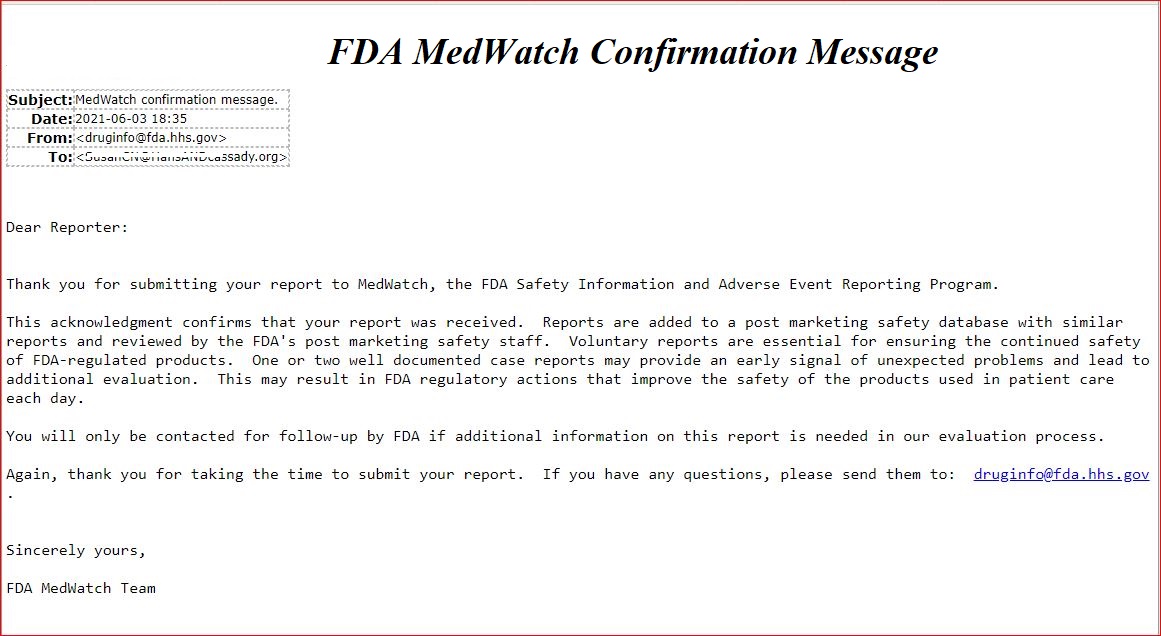
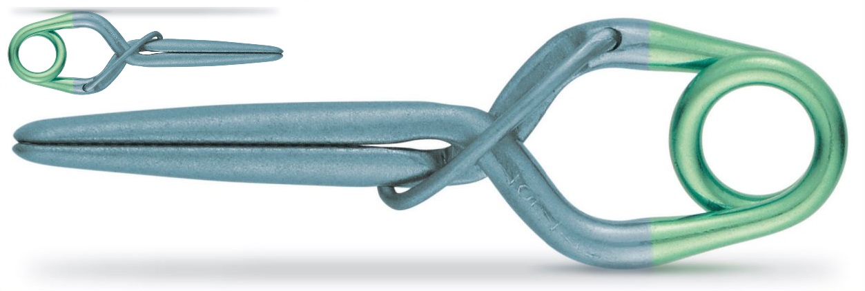
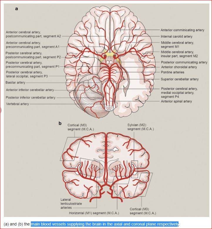

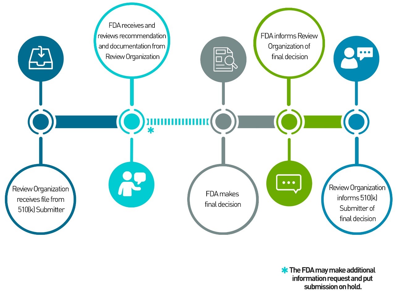

 " TITLE:...
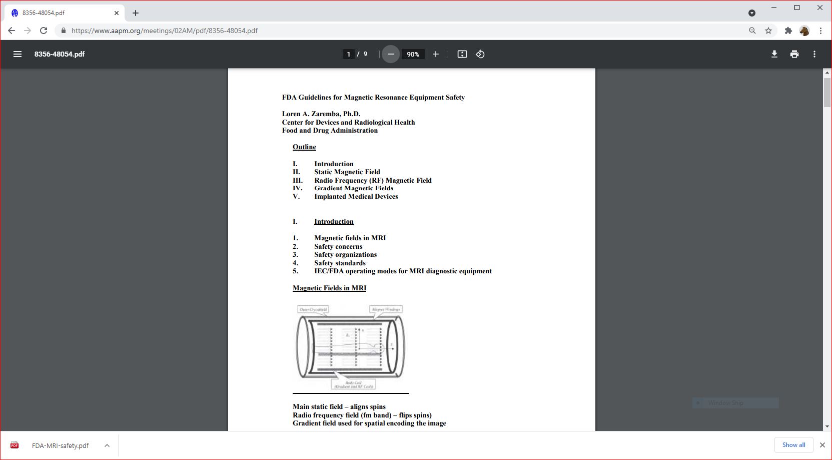
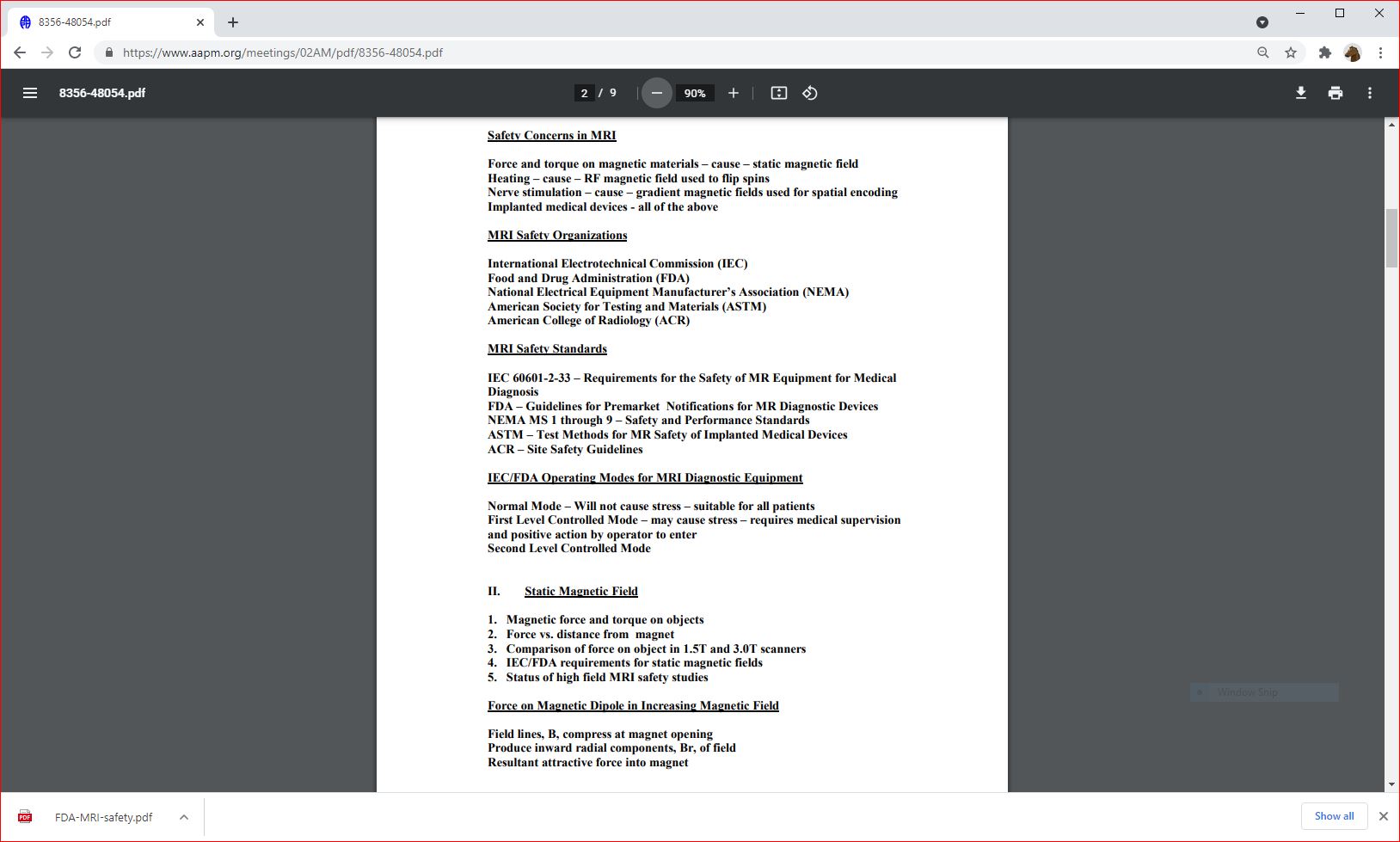
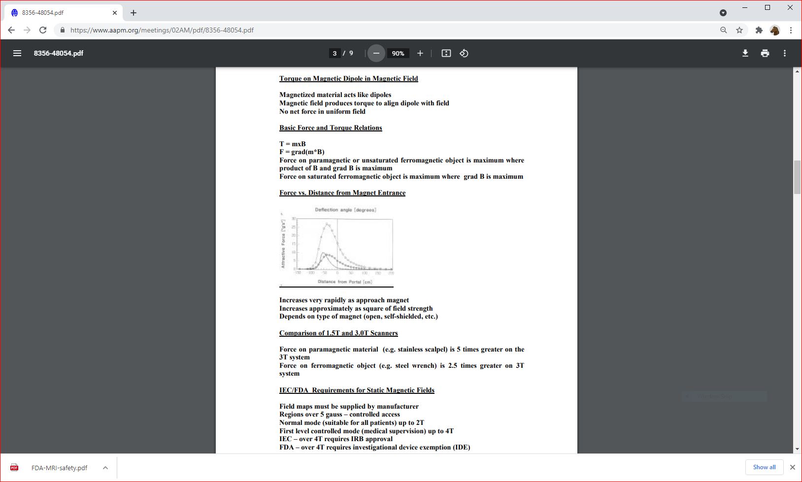
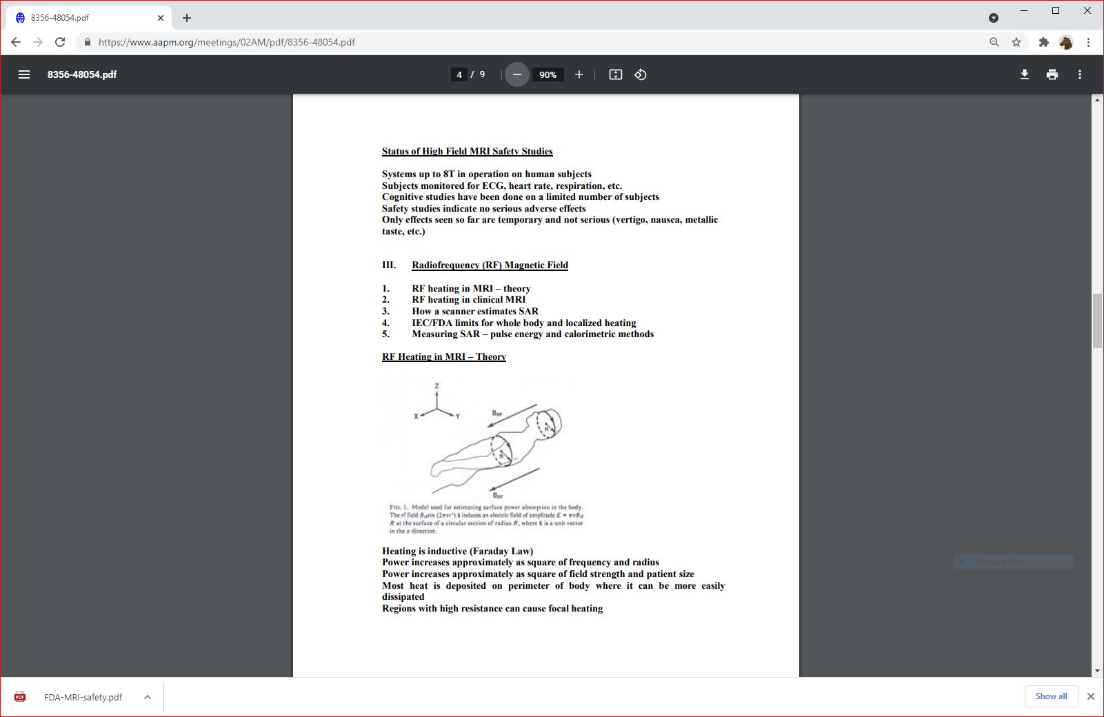
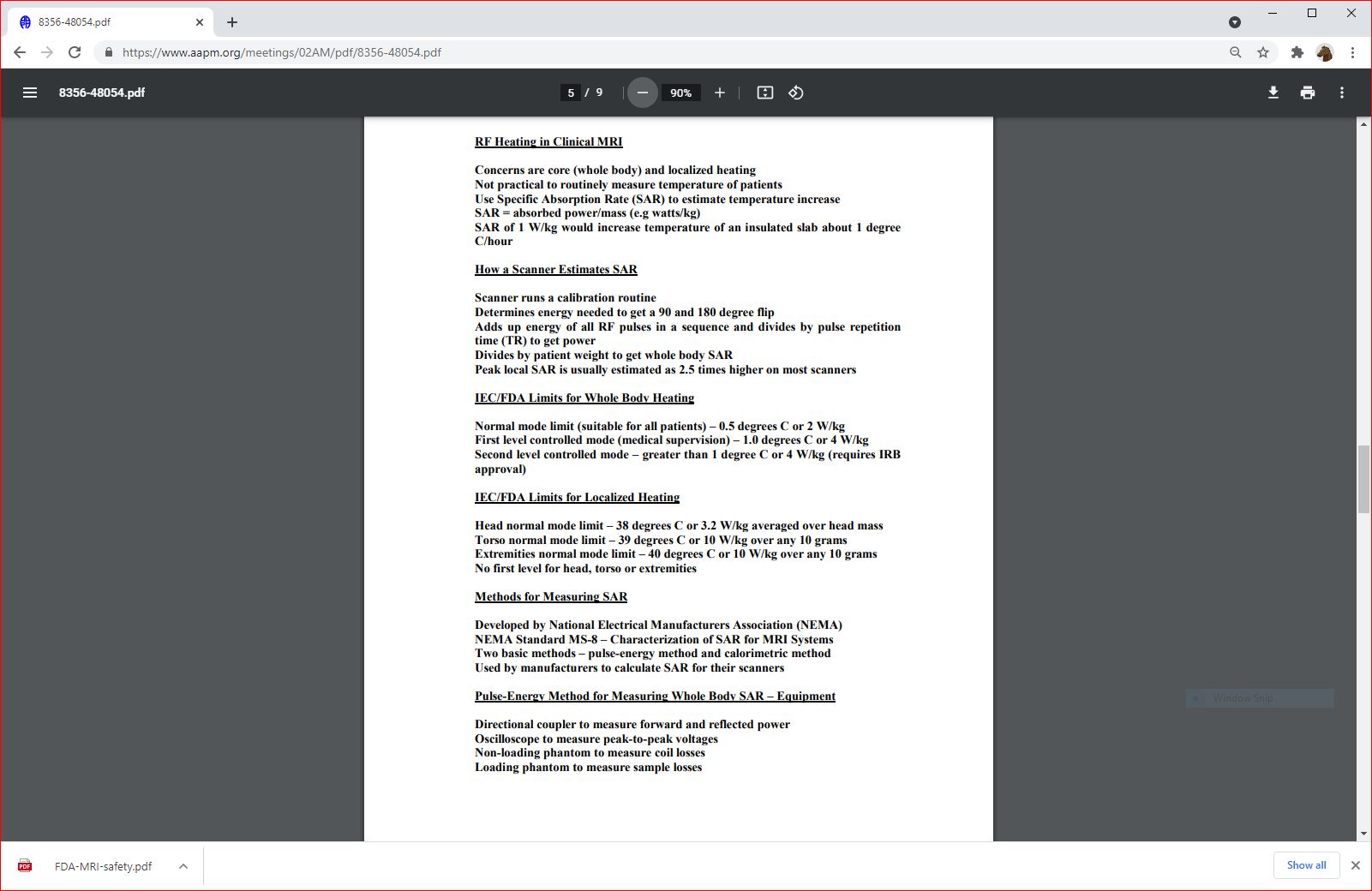
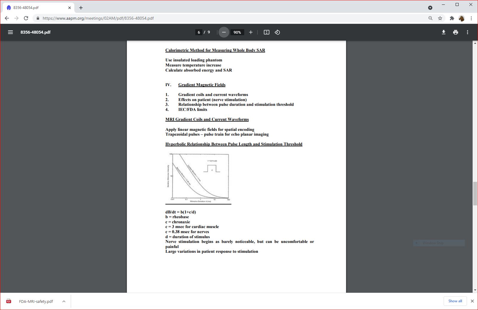
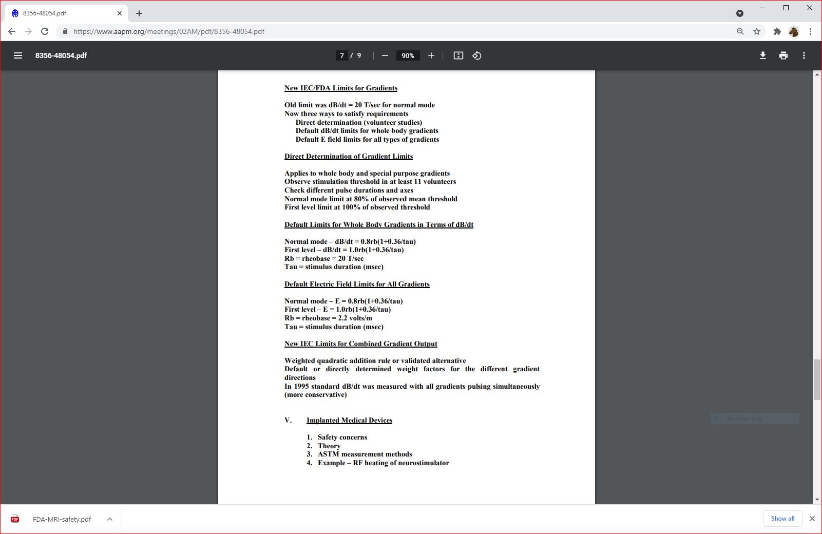

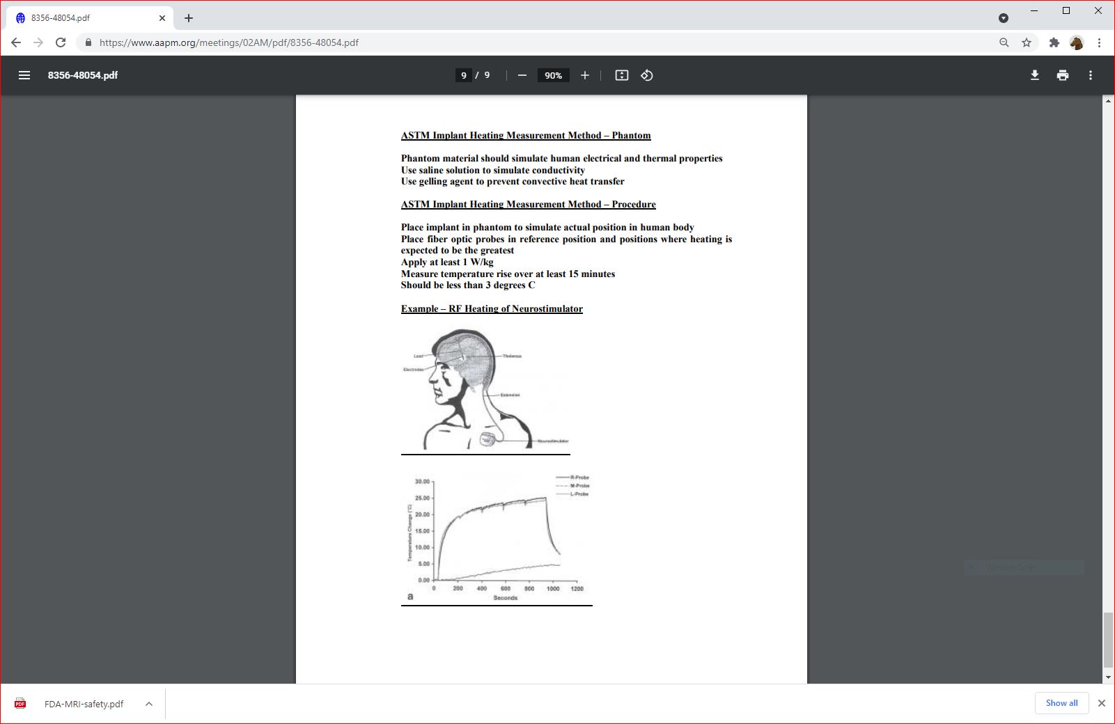
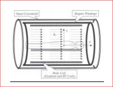
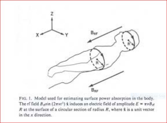
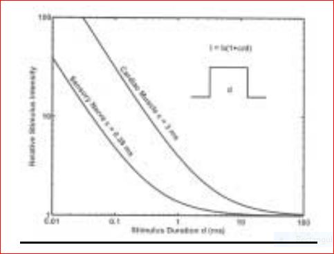
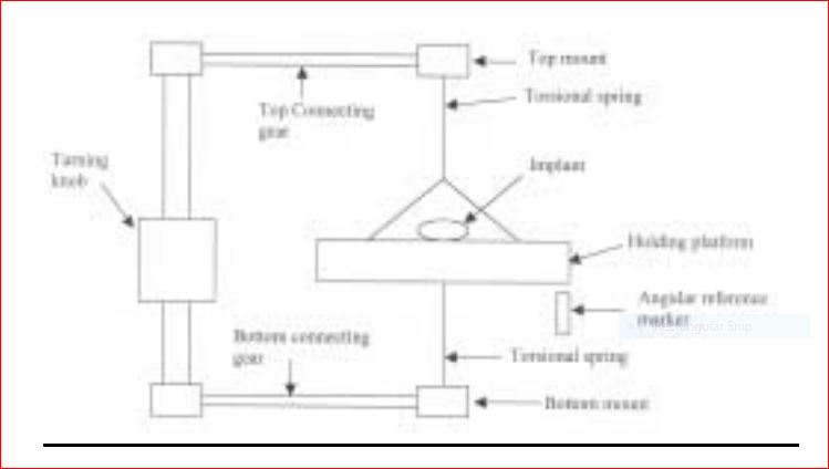
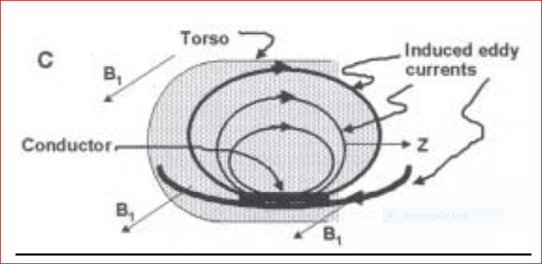
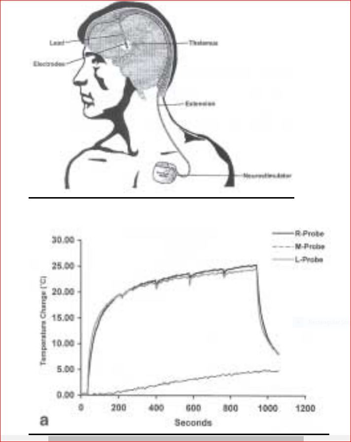
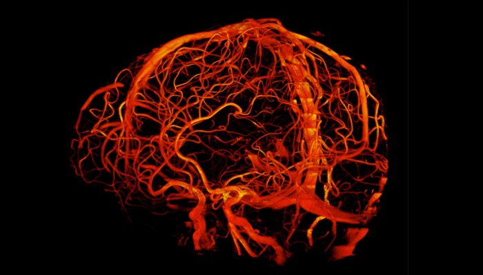
 hhhhh
hhhhh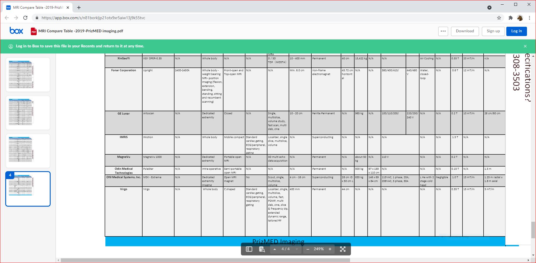 hhhhhhhhh
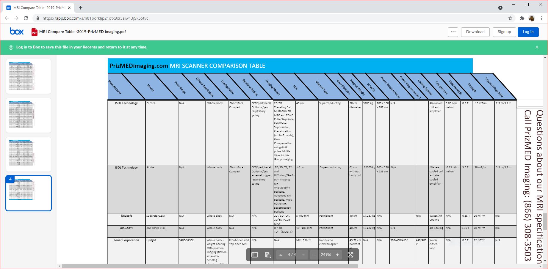 hhhhhhhhh
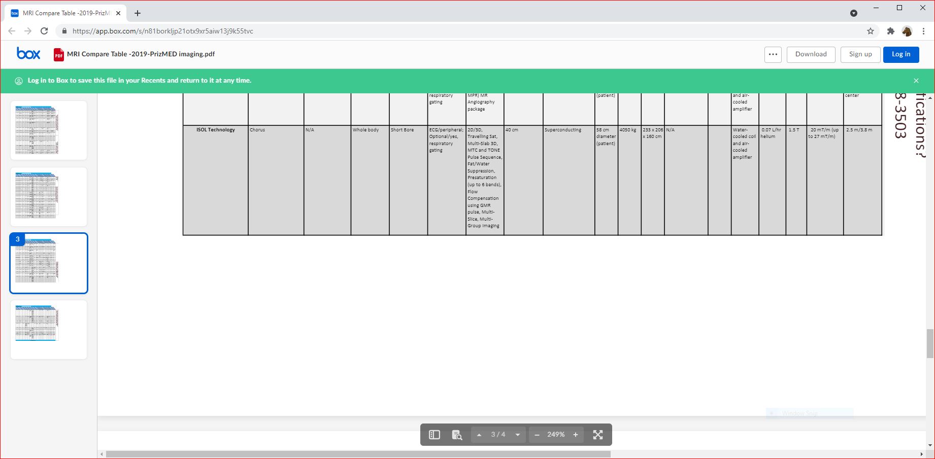 hhhhhhhhh
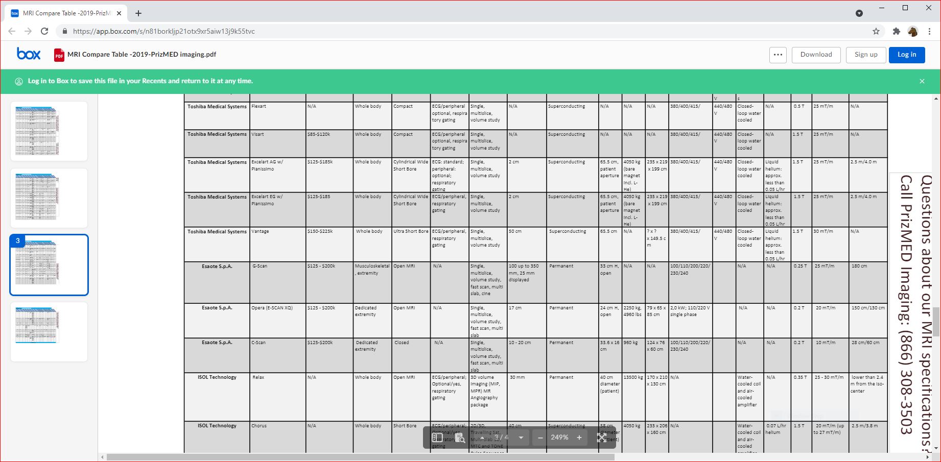 hhhhhhhhh
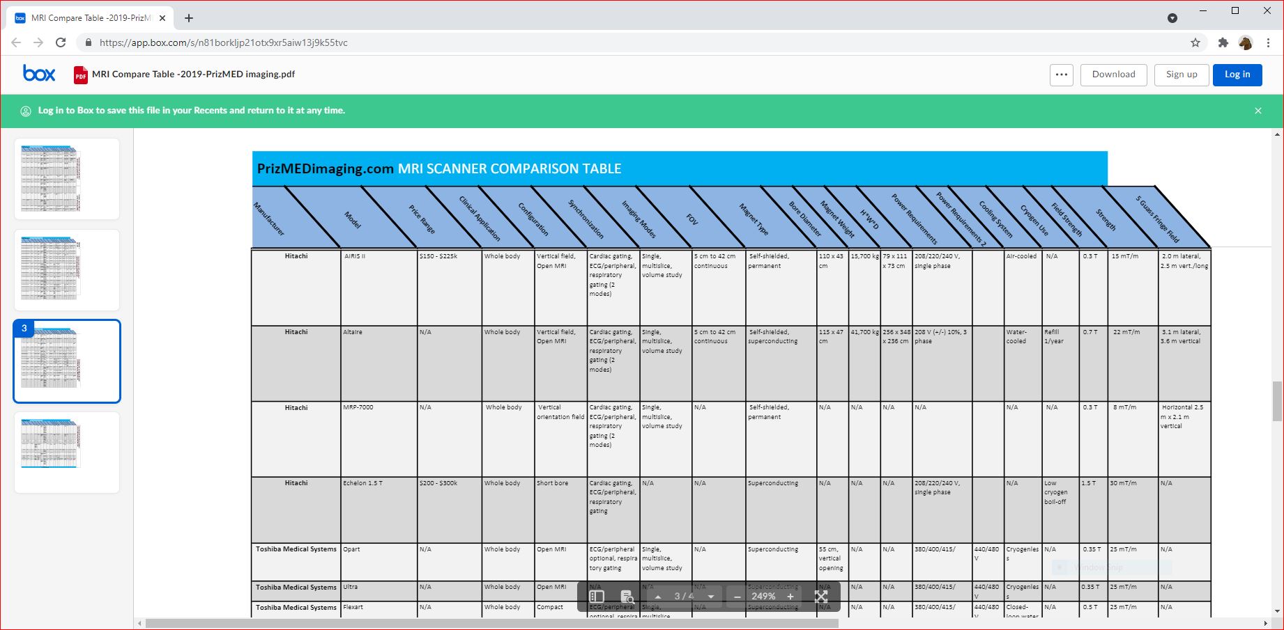 hhhhhhhhh
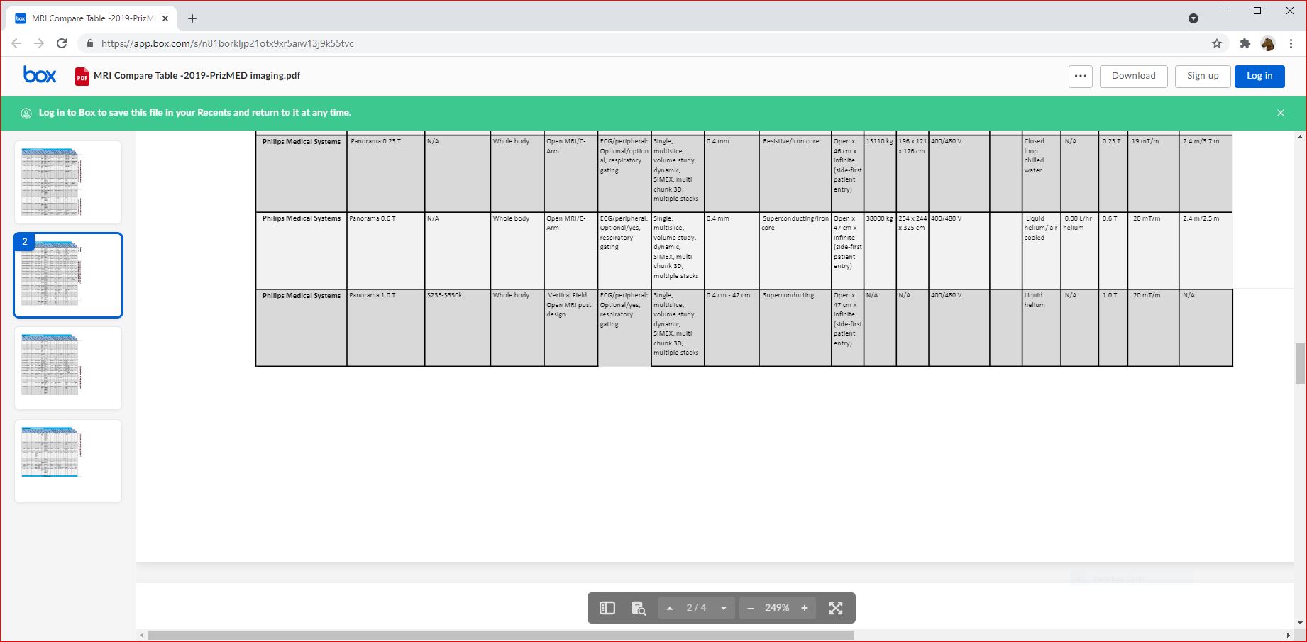 hhhhhhhhh
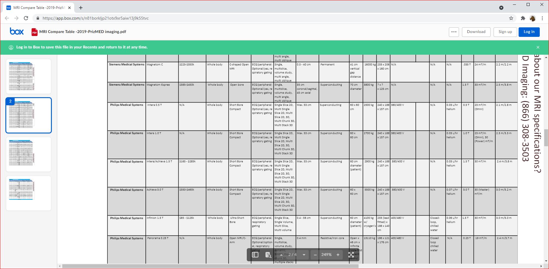 hhhhhhhhh
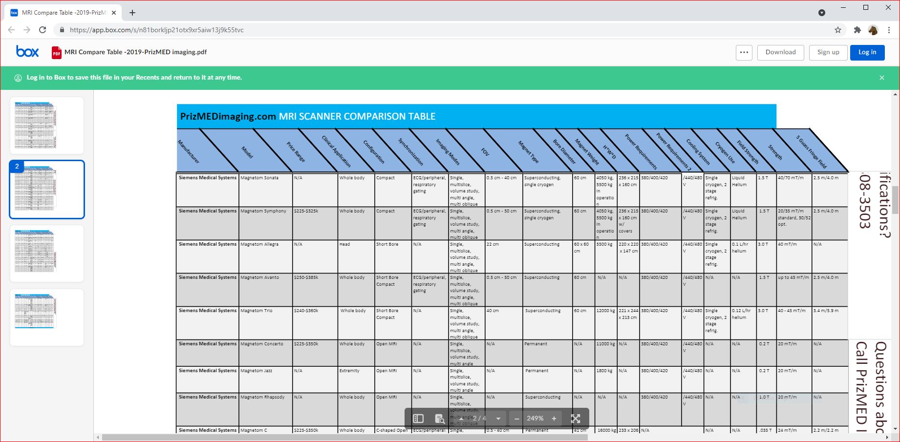 hhhhhhhhh
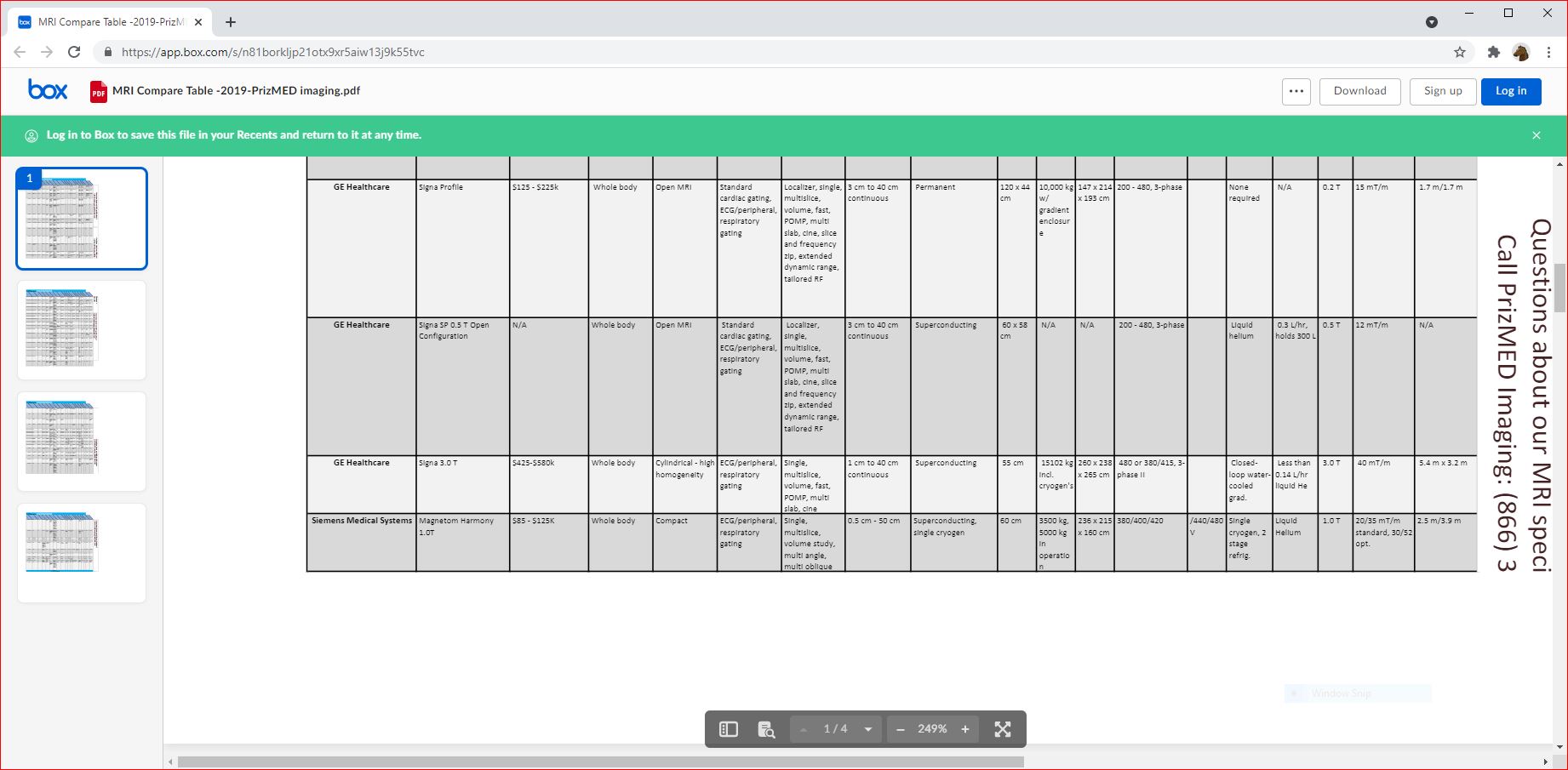 hhhhhhhhh
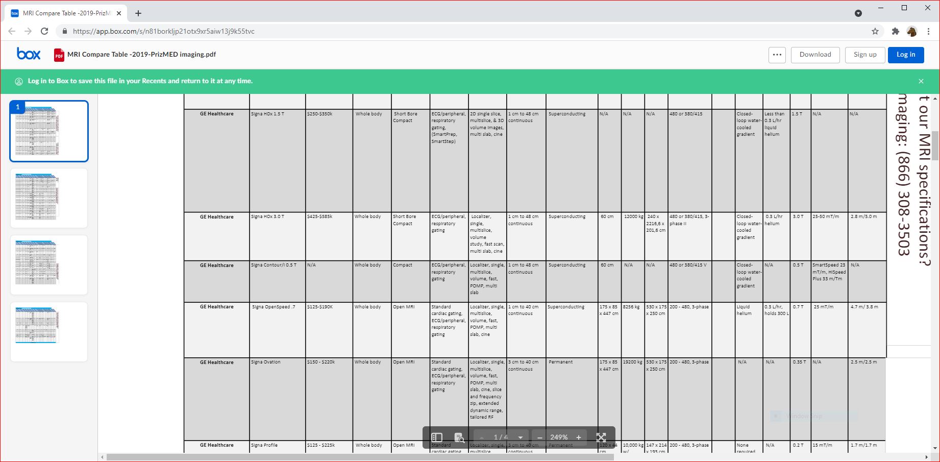 hhhhhhhhh
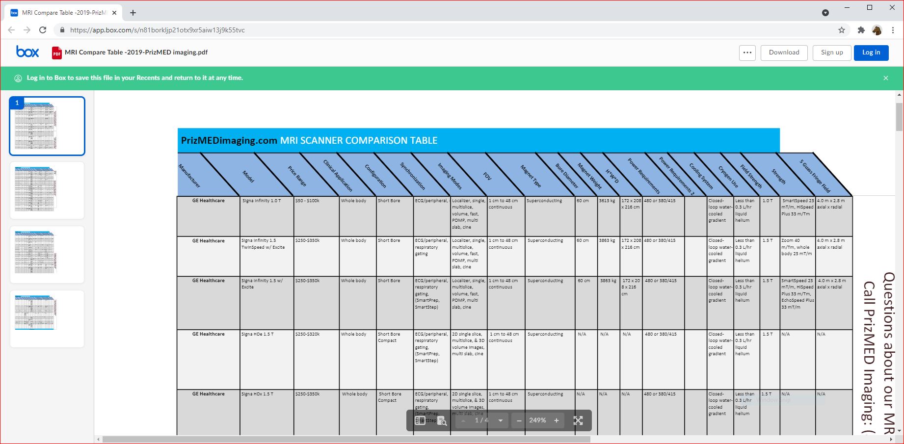

 MR imaging units consist of three primary systems, each with potential safety risks: (1) the main magnet, (2) gradient set, and (3) radiofrequency transmit-receive system.


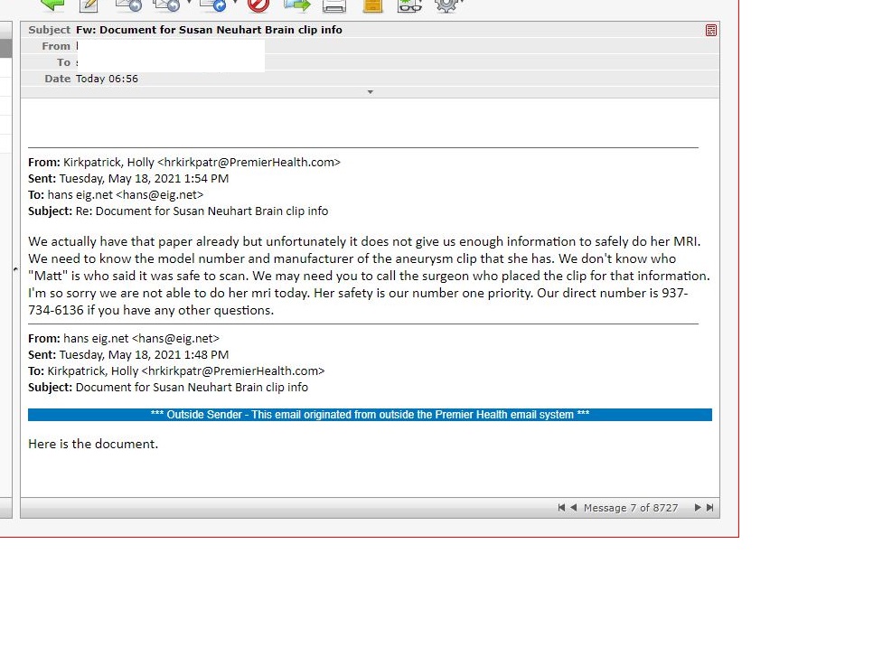 < MVH-North SAFETY
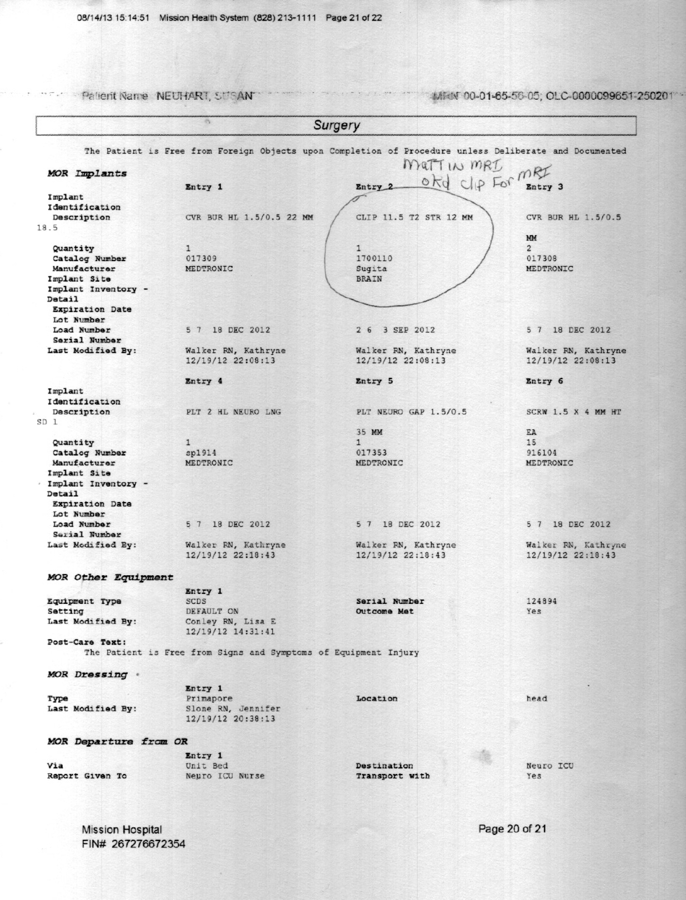 <
< 
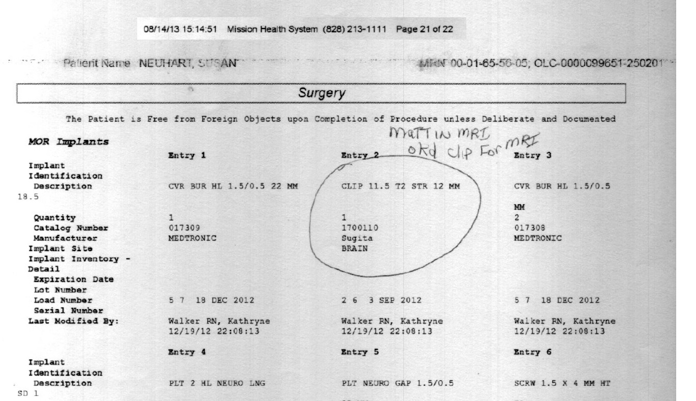
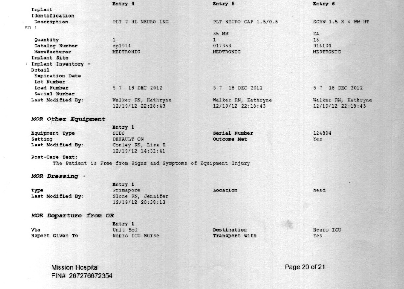