< home > updated 8-12-2021 - PAGE CREATED BY USA RETIRED SOFTWARE ENGINEERING TECHNICAL WRITER
- "shred", "edited" and hyperlinked - AS A PUBLIC SERVICE --
- And, the American mongrel (of Scottish descent) did live to tell his daughter. And, the daughter did think - IF this was possible - predicting WHAT would happen if... - THEN, IF the precise x, y, z position of ALL quantum particles could be known - at a moment in "precise time" - and their behavior predicted by "fundamental laws"
- THEN, we could create a "Crystal Ball" - in software - that was capable of prediction - of events - on any scale - based on ... [ algorithms ] :: AND, all that would be required - is "Translators" - to compose [and capture] "moments" [ glimpses ] perceivable by human customers - on demand.
TO CHARGE FOR A "PERFORMANCE" -IN SUCH DEMAND - MAKES ONE SO "WEALTHY" - MONEY HAS NO MEANING;
AND, ONE ONLY "PERFORMS" - WHEN ONE WANTS TO. INDEED, ONE IS A GOD - as this was understood by the Greeks - in a pantheon . ( Greek Pantheon: https://en.wikipedia.org/wiki/Twelve_Olympians )
Misconceptions of the Bumblebee: an in-depth Analysis of an Aerodynamic Marvel
December 9, 2011 at 2:03 am
You have probably all heard, at one point or another, that the bumblebee is nothing short of a scientific enigma – that our greatest minds, who have managed to place a man on the moon, have yet to explain the aerodynamics of the bumblebee’s flight. Unfortunately (or rather fortunately) this is all a misconception. Studies in recent years have done justice to explain just how the bumblebee manages to contradict known laws of aerodynamics.
The reason why the bumblebee has baffled scientists for so long is because its flight follows a pattern unlike any aircraft, animal, or even other insect thus far observed. Unlike, planes and birds, which use their wings to produce an ‘airfoil’ in order to generate lift, bumblebees rely on tiny movements and vibrations of their wings. This produces air vortexes around their wings, somewhat like a helicopter, and this lays the foundations for the bumblebee’s generation of lift.
Research teams at Oxford University performed a series of tests utilizing wind tunnels with smoke trails in order to study the bumblebee’s approach to flight. According to Doctor Bromphrey, “Our observations show that, instead of the aerodynamic finesse found in most other insects, bumblebees have a adopted a brute force approach powered by a huge thorax and fuelled by energy-rich nectar.” Since the bumblebee’s awkward shape prevents it from achieving aerodynamic efficiency, its wings must make up for this by beating up to 200 times per second. In fact, the bumblebee’s brain is hardwired to make these minute movements. Ultimately, this balance allows the bumblebee to be maneuverable albeit highly inefficient.
Images recorded by by a high-speed camera during the bumblebee's flight
Why the bumblebee’s evolution has led to this phenomenon continues to baffle scientists. One explanation is that since the bumblebee’s primary purposes are to obtain nectar from flowers and to consequently transport this nectar back to the hive, its form allows for it to contain a maximum amount of nectar however at the sacrifice of flight mobility and ability
The bumblebee's large size and relatively small wings allow for airborne maneuverability although with great inefficiency ...
In the past few decades, robotics research has witnessed an increasingly high interest in miniaturized, intelligent, and integrated robots. The imperative component of a robot is the actuator that determines its performance. Although traditional rigid drives such as motors and gas engines have shown great prevalence in most macroscale circumstances, the reduction of these drives to the millimeter or even lower scale results in a significant increase in manufacturing difficulty accompanied by a remarkable performance decline. Biohybrid robots driven by living cells can be a potential solution to overcome these drawbacks by benefiting from the intrinsic microscale self-assembly of living tissues and high energy efficiency, which, among other unprecedented properties, also feature flexibility, self-repair, and even multiple degrees of freedom. This paper systematically reviews the development of biohybrid robots. First, the development of biological flexible drivers is introduced while emphasizing on their advantages over traditional drivers. Second, up-to-date works regarding biohybrid robots are reviewed in detail from three aspects: biological driving sources, actuator materials, and structures with associated control methodologies. Finally, the potential future applications and major challenges of biohybrid robots are explored.
Graphic abstract
Introduction
Robotic technology has been rapidly developing in the past few decades and has already benefited humans in numerous heavy and repetitive tasks. Despite the predominant focus on large-scale robots, recent years have also witnessed an increased interest in intelligent micro-robots. Due to their small size, micro-robots can simulate the shape and movements of real organisms, allowing for operations that would be otherwise difficult to complete by traditional robots. For example, during earthquakes, micro-robots can move among ruins for search and rescue; or in medical treatments, they can enter the human veins for minimally invasive surgery.
A robot is mainly composed of drivers, control systems, executing mechanics, and sensors [1,2,3]. Among them, the driver as the power conversion component of the robot determines its motion patterns and performance. The key to the design and manufacture of micro-robots is the miniaturization of the drivers. Micro-robot drivers can be divided into three categories: traditional rigid drives [4,5,6,7,8], flexible material drives [9,10,11,12,13], and biomaterial drives [14,15,16,17,18].
Traditional rigid drives include hydraulic, pneumatic, and the most commonly used electromagnetic motor. For example, the cockroach-like robot developed by Najafi’s group [19] and the fruit fly-like robot developed by Croon’s group [20] use the motor to realize walking or flying motions. Although this traditional driving technology is supported by well-developed control theories and sophisticated manufacturing processes, its operating principle is quite different from that of the real organism resulting in its incapability to accurately simulate its motion characteristics. More importantly, when the size of the driver needs to be reduced to the millimeter-scale or smaller, the manufacturing difficulty of traditional drivers sharply increases, while their output force and power density decrease exponentially (millimeter scale, maximum output force about 10 μN, output power density < 0.01 kW/kg) [21, 22]. Meanwhile, its unsatisfying reliability, relatively short lifespan, low energy efficiency, and other defects at the miniature scale become deteriorated. For instance, the battery-powered fully charged bee-like micro-robot developed by Harvard University can only fly for a few seconds [7]. The hummingbird robot driven by two motors developed by Purdue University can merely fly for 1.23 min at most [23].
Faced with the defects of conventional rigid drivers, new driving methods via using flexible stimuli-active materials such as dielectric elastomer actuator (DEA) [24,25,26], shape memory alloy (SMA) [27,28,29], and liquid crystal elastomer (LCE) [30,31,32,33] are developed. For example, Wood’s [34] team developed a flying robot driven by multilayer dielectric elastomers, which can perceive and withstand collision with obstacles and recover from collisions by taking advantage of the robustness of the material and the passive stability of the machine. Compared with traditional driving methods, this flexible material drive can be powered by electrical stimulation at the millimeter or even smaller scale, and among other advantages, has better self-repair capability and reliability. However, due to the lack of in-depth research on stress, strain, response speed, efficiency, and lifespan, research on flexible material drivers is still in its infancy, and certain disadvantages, such as low power density and high driving voltage, are still hindering its practical applications.
In contrast, with the development of interdisciplinary subjects in bioengineering, nanotechnology, and three-dimensional (3D) bioprinting [35,36,37,38,39], the combination of biological living actuators and nonliving biomaterials became a possible solution for overcoming the limitations of existing driving methods. Compared with the traditional rigid-driven and flexible material-driven robots, biomaterial-driven biohybrid robots (also known as biobots) can better recapitulate the microstructures and motion patterns of living organisms, with remarkable advantages of high controllability, output force, and power density at the millimeter and smaller scales, accompanied by the potential of self-assembly, self-repair, and self-replication capabilities [40,41,42,43,44]. For example, the micro-robot designed by Bashir et al. [45] can carry out accurate multidirectional and steering motion under the action of light stimulation, which shows high controllability and energy efficiency.
In nature, living creatures usually show high flexibility and energy conversion efficiency and thus may hopefully be the models of a new generation of robots. Biohybrid robots with unprecedented biomimicry in driving performance can potentially yield great applications in mechanics, biomedicine, material science, chemical engineering, and many other fields. This review aims to give a comprehensive review of the up-to-date developments of biohybrid robots. The present section provides an introduction to biohybrid robots. Next, an in-depth review of the related research on the driving technology of micro-biobots is presented. Considering biology, material science, machinery, and other relevant disciplines, we describe the biobots from three main aspects: biological composition, underlying materials, and structure/control mechanisms, while highlighting the latest progress of each field. Finally, we discuss and summarize the potential applications and future challenges of biohybrid robotics research.
Living driving sources used for biohybrid robots
Most traditional rigid robots and soft material robots are unable to meet the requirements of miniaturization and energy efficiency at the same time. A new type of driving source with high flexibility and driving force is therefore urgently needed to satisfy the size and output force demands of robots [46,47,48,49]. Many naturally evolved living tissues can produce the necessary driving forces with durability, and they can potentially be used as ideal drivers for micro-biobots. Xi et al. [50] first proposed a biological robot in 2005, which opened a Pandora’s box and triggered rapid developments in this field for the next 15 years. According to biological composition, biological driving sources can be roughly divided into five categories: mammalian primary cells [51,52,53,54,55], mammalian cell lines (mainly cardiomyocytes and skeletal muscle cells) [14, 56,57,58,59], insect dorsal vascular tissue (DV tissues) [60,61,62,63], microorganisms [64,65,66,67,68] and others (sperm, T cells, etc.) [69,70,71,72,73] (shown in Fig. 1 and Table 1). The latest developments of each category is reviewed in the following chapters.
Fig. 1
The top of the figure shows some major milestones in biomaterial-driven bio-robot research from 2005 to 2020. The overall design process of a biological robot made up of primary cells, cell lines, dorsal vascular (DV) tissue, and microorganisms is demonstrated at the bottom
The top of the figure shows some major milestones in biomaterial-driven bio-robot research from 2005 to 2020. The overall design process of a biological robot made up of primary cells, cell lines, dorsal vascular (DV) tissue, and microorganisms is demonstrated at the bottom
Herein, the reference to primary mammalian cells generally means the cell suspension extracted from mammalian organs or muscles, which can form new muscle tissue after tissue culturing. The most commonly used cells of this type are primary cardiomyocytes and primary skeletal muscle cells extracted from newborn mice. The muscle actuators of these two types of cells have been widely used in biohybrid robots due to sufficient developmental plasticity, which allows them to be planted on extracellular materials to form integrated devices.
Primary cardiomyocytes
These cells are generally isolated from the ventricles of infant rats and then planted on artificial materials to form muscles. Primary cardiomyocytes feature spontaneous and synchronous contraction after being implanted onto artificial materials and cultured for 2 days, and generally reach stability after 6 days [74,75,76]. The approximate size of a single cardiomyocyte is 100 μm × 100 μm × 10 μm, and its rhythmic contraction can produce a force of about 10 μN [77]. The maximum output force will further increase as muscle cells differentiate into muscle tissues, becoming larger than the driving force of traditional robots proportionally shrunk to the same microscale. As a result, cardiomyocytes are widely used to drive various biological robots to achieve deformation, walking, grasping, and other operations.
In 2005, for example, Xi et al. [50] developed the first walking robot with the ability to move autonomously (138 μm long and 40 μm wide legs), and the study laid the foundations for follow-up developments. Driven by the spontaneous contraction of cardiomyocytes, the maximum speed of their robot can reach 38 μm/s after 3 days of culturing. Similarly, Bashir et al. [78, 79] presented a cardiomyocyte-driven mobile robot consisting of a “biological bimorph” cantilever structure and an asymmetrically shaped base, as shown in Fig. 2a. The optimal size of the cantilever beam was established as 7 mm × 2 mm × 182 μm. The contraction of cardiomyocytes causes the retention of the asymmetric structure and subsequently drives the robot to walk with a maximum speed of 236 μm/s. In the same year, Parker’s team [80] developed a more complex jellyfish robot by combining computer-aided design with physiological performance, as shown in Fig. 2b. The speed of muscle contraction and relaxation can be controlled by electrical stimulation, which can drive and control the jellyfish-shaped polydimethylsiloxane (PDMS) film to swim toward a specified direction.
Fig. 2
Examples of biobots based on mammalian primary cells: a Biobots consisting of a biological bimorph cantilever with seeded cardiac cell sheets (reproduced with permission Ref. [79]); b jellyfish muscle architecture with customized functionalities contracted by properly aligned cardiomyocytes (reproduced with permission Ref. [80]); c a phototactic device driven by muscle tissue composed of cardiomyocytes (reproduced with permission Ref. [81]); d the crawling process of the soft robot driven by cardiomyocytes and color variation during the movement process (reproduced with permission Ref. [53]); e a biobot powered by a pair of primary skeletal muscle tissues with biomimetic motion and its operation (reproduced with permission Ref. [86]); f construction of a biohybrid robot with the skeletal muscle tissue covered with a collagen structure (reproduced with permission Ref. [51])
Although cardiomyocytes can contract spontaneously, the ability to perform designed and controllable maneuvers is a more preferable asset of a biobot. Based on their previous research, Parker et al. designed a batfish robot in 2016 [81] (shown in Fig. 2c). The cardiomyocytes were modified by cell and genetic engineering and cultured on an elastomer wrapped in a miniature metal skeleton, such that they were distributed in a serpentine pattern. Through controlling the light position to stimulate the local contraction of cardiomyocytes, this batfish can swim at a speed topped at 3.2 mm/s. When the motion control is realized, it is desirable to observe the motion state of the robot directly through the naked eye, which triggers research on visually observable feedback robotics. Zhao’s team developed a caterpillar-like robot in 2020 [53] (Fig. 2d) via the secondary polymerization of carbon nanotube hydrogel to form structural color-changeable hydrogel stimulated by cardiomyocyte contractions. The orderly arranged silica nanoparticles produce a photonic bandgap structure, which results in the vivid structural color of hydrogel [82,83,84]. The motion state of the robot can thus be observed directly via scanning the color spectrum for changes. Moreover, under the action of a weak magnetic field, the robot can simulate the crawling behavior of caterpillars and realize autonomous directional movement.
Although primary cardiomyocytes have the advantages of natural biocompatibility, high efficiency, and high driving force, their spontaneous contractions hinder the precise control of cells to achieve complex tasks. Moreover, their lifespan is relatively short with the output power gradually decreasing during one-week of culture [76].
Primary skeletal muscles
In comparison with the volume of research on primary cardiomyocytes, fewer studies exist on primary skeletal muscle cells. Despite their relatively short lifespan (several hours to a few days), primary skeletal muscle cells do not contract spontaneously, which allows for higher controllability and activities that are more dynamic and complicated [47].
In 2013, Morishima et al. [85] designed a living prosthesis driven by skeletal muscle. When the muscle is electrically stimulated, its “hand” is actuated to move. Despite its high controllability, skeletal muscle lacks consistency in the time dimension due to inherent internal traction during culturing. Given that, Takeuchi et al. [86] designed a biobot driven by a pair of antagonistic skeletal muscle tissue blocks to balance internal traction, as shown in Fig. 2e. Under 50 Hz electrical stimulation, the robot can achieve 90° rotation movement by selectively actuating a specific muscle tissue, allowing the robot to grasp and place small objects. With the problem of intrinsic contraction solved, the lifespan of the robot can also be extended to over a week.
Although biobots driven by skeletal muscles can achieve all kinds of movements, the problem remains that they can only operate in culture medium instead of ambient air. In 2020, based on their previous research, Takeuchi’s team developed a biobot capable of moving in the air [51], as shown in Fig. 2f. The robot wraps skeletal muscle tissue and flexible substrate material in a collagen structure to maintain the necessary humidity in the air. Results showed that the robot maintains high cell activity and contractility in the air and can bend under the action of electrical stimulation. Moreover, driving time can be greatly increased up to 1 h by using culture medium perfusion, which is four times longer than that without perfusion.
Research on primary skeletal muscle-driven biobots has made great progress to date; however, challenges still exist in using primary cells because of their relatively short lifespan and potential ethical problems due to the associated animal sacrifice.
C2C12 skeletal muscle cells
Skeletal muscle cell lines (such as C2C12) are more popular in research than derived cardiomyocytes, as they offer ideal power sources for biobots that require full controllability and a modular design. Skeletal muscle is formed by parallel fiber bundles. Mechanical and electrical stimulation can promote cell differentiation into muscle [87,88,89], strengthen muscle functions, and drive the movements of biobots. In addition, the energy supply of skeletal muscle cells comes from adenosine triphosphate (ATP), which is more effective than conventional motor drives at the microscale. Therefore, extensive research has been carried out on numerous robots driven by skeleton muscle cell lines. For example, Bashir et al. [90] developed a biped beam robot with asymmetric structure through 3D printing for performance optimization, as shown in Fig. 3a. The biobot can reach a maximum unidirectional moving speed of 156 μm/s (the size of the robot is 6 mm × 3 mm × 1.2 mm). The robot is also the first untethered biological robot driven by skeletal muscle that is fully controllable by external signals. However, it still has two limitations, in that (1) structural adaptiveness is limited due to fixation of muscle rings and (2) unidirectional moving pattern is a barrier of its maneuverability. The same group subsequently designed a quadruped robot driven by C2C12 skeletal muscle cells modified by a photosensitive stimulator [45], as shown in Fig. 3b. Skeletal muscle cells differentiate into muscle rings, which can achieve a directional movement by local light stimulation on a single muscle ring. Also, the muscle rings can be manually transferred to a wide variety of biobot skeletons. On this basis, the team proposed a modular skeletal muscle design method [91]. The millimeter actuator can be used to actuate various 3D-printed skeletons (such as biped beam, quadruped beam, and even octopod robot), thus improving the versatility of the drive.
Fig. 3
Examples of biobots based on mammalian cell lines. a Bipedal robot driven by C2C12 skeletal muscle and its manufacturing method (reproduced with permission Ref. [90]); b preparation of muscle ring for driving a robot (reproduced with permission Ref. [45]); c a modular approach to the design, fabrication, and characterization of muscle-powered biological machines (reproduced with permission Ref. [95]); d general coculture platform of neuron and muscle (reproduced with permission Ref. [96]); e a miniature pump powered by frozen cardiomyocytes (reproduced with permission Ref. [100])
Electrical stimulation and light stimulation are common methods to control skeletal muscle, but their mechanisms are still different from that of real organisms. The movements of real organisms are achieved by the transmission of electrical signals through neural networks, which stimulate and drive the contraction and relaxation of muscle tissue, thereby coordinating the movements of specific body parts [92,93,94]. It was not until 2019 that a step toward this goal was demonstrated by Saif et al. [95] in the form of a double-tailed swimmer robot driven by nerves and muscles (shown in Fig. 3c). Therein, the muscle tissue formed by C2C12 skeletal muscle cells was cocultured in situ with neurons, causing the selective extension of motoneuron axons to muscle tissue to form a functional neuromuscular unit. Upon light stimulation, the neuromuscular-driven robot can swim at a speed of 0.7 μm/s in liquids with a low Reynolds coefficient. On this basis, the team designed a general 3D neuromuscular coculture platform [96] (shown in Fig. 3d). The platform allows for coculturing neuron clusters with up to four target muscles and for quantifying the muscle contractile force. It also provides the means to further explore the role of synergy in the development of neuromuscular biological drivers.
Given the advancements of research in recent years, mammalian muscular cells, whether primary cells or cell lines, seem a highly promising driving source for biobots. However, they also have drawbacks such as a relatively short lifespan, dependence on culture conditions (nutrients, oxygen, temperature, pH), and other in vivo conditions to properly function.
Cardiomyocytes derived from stem cells
Research on mammalian primary cell lines played a remarkable part in the development of transformed cell lines used for muscle tissue to drive biobots, which are discussed in this section.
Cardiomyocytes can be formed by inducing the differentiation of stem cells via chemical, electrical, or other stimulation methods [97]. Since the number of cardiomyocytes is normally constant in living organisms, cell lines of this type are generally difficult to obtain. Unlike primary cardiomyocytes that can be connected to cell slices to boost output force [59], separated cardiomyocytes can merely generate a limited force. Due to these reasons, attention is paid to optimizing the structural design of biobots driven by this cell type. For instance, Tanaka et al. [59] constructed micropumps from frozen rat cardiomyocytes, which collect the forces generated by cardiomyocytes through membranes and cubes, and transfer them to pump fluids. The theoretical flow rate of their micropump can reach 6.3 nL/min, which is consistent with that of the previous micropumps formed by primary cardiomyocytes [98, 99], proving the feasibility of microdevices driven by stem cell-derived cardiomyocytes. The same team further developed a new type of micropump drive system [100] (shown in Fig. 3e) by inducing the differentiation of mouse embryoid cells to form cardiomyocytes in situ. After two weeks of culture, a periodic oscillation of the pump can be observed, and the theoretical flow rate is 6.9 nL/min, which also reaches that of micropumps driven by primary cardiomyocytes. However, the complexity and cost of inducing stem cells to differentiate into cardiomyocytes are existing challenges, and it is crucial to have an optimized control of culture conditions for practical application.
Insect dorsal vessel (DV) tissue
The central pulsating blood vessel on the back of insects plays the role of the heart, which contracts at a constant frequency without any stimulation. It contains DV tissue that, as another actuation source, shows many distinctive properties that surpass its mammalian counterparts. For example, insect tissues can survive under a wider range of external and internal environmental conditions, such as a temperature range of 0–55 °C and a pH range of 4–11. Some insect tissue can even survive complete hypoxia for several days [101]. In terms of lifespan, robots driven by insect DV tissue can live for up to 90 days without the need for medium change, which is much longer than that of biobots driven by mammalian cells [102].
Morishima et al. [103] developed an insect muscle-powered autonomous micro-robot, the maximum speed of which can reach 257 μm/s, which is faster than that of previously reported biobots [50, 104]. In the footsteps of that project, they developed a biological driver that can operate in the ambient environment, and consists of DV tissue, micro-tweezers, and capsules [105] (shown in Fig. 4a). The self-shrinking driving tweezers can be turned on and off by transferring the actuator from the medium to the air. Moreover, the service life can be extended from about 40 min to 5.2 days by pouring liquid paraffin on the surface of the capsule. This study shows the great potential of insect DV tissues as biological drivers operable under ambient environment.
Fig. 4
Examples of biobots based on DV tissues and microorganisms. a The schematic design and actual digital images of the biohybrid tweezer power by packaging insect DV tissue in culture medium to expand the application range (reproduced with permission Ref. [105]); b an autonomous swimming biobot driven by autonomous pulsation of DV organization (reproduced with permission Ref. [62]); c a biocompatible biohybrid microswimmer powered by a unicellular freshwater green microalga (reproduced with permission Ref. [121]); d biohybrid bacteria-driven microswimmers and a three-channel microfluidic concentration gradient generator (reproduced with permission Ref. [124]); e a multifunctional microswimmer consisting of a single Escherichia coli attached to the surface of drug-loaded polyelectrolyte multilayer particles embedded with magnetic nanoparticles (reproduced with permission Ref. [125]); f a biobot with immunogenicity formed by the interaction between nano-red blood cells and Escherichia coli (reproduced with permission Ref. [126])
In 2019, Morishima et al. proposed a swimmer prototype driven by DV tissue [62] (shown in Fig. 4b) that reaches an average swimming speed of 11.7 μm/s. Although the robot is slower than some other swimming robots [106], the provided driver solution is a low-cost, biomimetic, and conveniently available option.
Insect-derived drivers provide alternatives to biological actuators and are of particular interest in robotic applications for harsh environments.
Microorganisms
In addition to biobots driven by muscle cells, microorganisms are also widely used to actuate biobots [107,108,109,110,111]. Microorganisms have the advantages of small size, low weight, high speed, and high viability [112, 113]. Furthermore, they have the ability to show magnetotaxis, chemotaxis, and responses to other physio-chemical stimuli. Microbial robots can mainly be divided into those driven by microalgae [114, 115] and bacteria [116,117,118,119].
With respect to microalgae, Liu et al. [120] developed a method to control microswimmers based on phototaxis. Under the guidance of 490 nm light-emitting diode (LED) light, microswimmers can be controlled to swim back and forth, and successfully realize the movements along zigzag, triangle, and other arbitrarily set trajectories, showing great significance for transporting drugs in the field of biomedicine. In 2018, Sitti et al. built a biobot based on the interaction between a negatively charged Chlamydomonas reinhardtii [121] and positively charged polyelectrolyte (PE) functionalized magnetic polystyrene (PS) particles, as shown in Fig. 4c. Under the implementation of a 26 mT uniform magnetic field, the average speed of the microswimmers reaches about 150 μm/s, which is much faster than that of most other microswimmers [122, 123]. Moreover, their microorganism-based robot shows good cytocompatibility, steady performance and survivability under physiological conditions and can be manufactured by relatively simple procedures.
Compared with microalgae, bacteria-driven robots have been more commonly studied and developed. For example, Sitti et al. [124] first elucidated the basic physical mechanisms of a seemingly synergistic chemotaxis between multiple bacteria attached to the same microstructure by studying a biological hybrid microswimmer system driven by multiple Serratia marcescens cells, as shown in Fig. 4d. Results showed that the heading deviation of microswimmers is the main factor leading to chemotactic drift. On this basis, they developed a high-performance multifunctional microswimmer in 2017 [125], which features a single E. coli cell attached to the surface of drug-loaded polyelectrolyte multilayer (PEM) particles embedded with magnetic nanoparticles, as shown in Fig. 4e. Biased and directional motion can be realized under the gradient of the magnetic field and chemical attractants, and the drift velocity under chemical stimulation (2.0 μm/s) is higher than that achieved in previous studies (0.66 μm/s).
Although bacteria-driven swimming robots have great potential, especially in biomedical drug transport, their immunogenicity and low motor performance still pose great challenges. A forward step was made by Sitti’s team, who developed a robot formed by the interaction between E. coli and nano-red blood cells [126], as shown in Fig. 4f. The robot not only has no immunogenicity, but also higher speed performance (14.06 ± 6.71 μm/s) than other robots driven by E. coli, thus providing a reference for follow-up research.
Other biological components
In addition to common mammalian muscle cells and DV tissues, many other biomaterials have been studied as driving sources for biological robots, such as sperm cells, macrophages, non-mammalian cardiomyocytes, or muscle tissues of Drosophila larvae. For example, Tanaka et al. [127] developed a new type of micropump (size is 2 cm × 2 cm) made of natural earthworm muscle and PDMS microchip (shown in Fig. 5a). Upon the application of electrical stimulation, the muscle tissue generates a maximum force of 9.33 mN. Meanwhile, the flow rate can reach 5.0 μL/min, which is 3–4 magnitudes higher than that of a previously reported cardiomyocyte pump and comparable to those of the traditional pump [128,129,130]. Morishima et al. used similar methods to develop a micro-peristaltic pump from the light-responsive muscle obtained by ChR2 genetically engineered fruit fly larvae [55], as shown in Fig. 5b. Under the stimulation of blue light, it can transport beads at a speed of 120 μm/s.
Fig. 5
Examples of biobots based on other biological components. a Micropump prepared from earthworm muscle tissue (reproduced with permission Ref. [127]); b light-responsive muscles obtained from Drosophila larvae are made into micro-creeping tubes that can transport microbeads (reproduced with permission Ref. [55]); c spermbots consisting of single sperm cells captured in artificial magnetic microstructures (reproduced with permission Ref. [131]); d a method of manufacturing a biological robot composed of macrophages (reproduced with permission Ref. [133])
In addition to the muscle tissue obtained from animals such as larvae, sperm is also a biomaterial that has attracted attention because of its extraordinary motion performance. Khalil et al. [131] studied the hydrodynamic effects of a sperm robot composed of bull sperm cells and microtubules (shown in Fig. 5c) in a heterogeneous viscous medium similar to the in vivo environment. It was revealed that the driving force of the sperm robot can be increased by shortening the microtubule size and increasing the magnetic moment. Based on this result, they compared the driving characteristics of active sperm cells with magnetically driven dead sperm cells [132], which provided an insight into the structural design of microswimmers. Furthermore, Park’s team developed a macrophage micro-robot [133] (shown in Fig. 5d) that consists of phagocytosis of iron oxide (Fe3O4) nanoparticles and poly(lactic-co-glycolic-acid) (PLGA) nanoparticles encapsulated by docetaxel (DTX) in a mouse-derived macrophage line. Driven by the electromagnetic actuation (EMA) system, the robot can target tumor cells and show a potential in targeted therapies.
Extracellular materials for biohybrid robots
A further important component of biohybrid robots is the substrate material [134,135,136,137]. Since the substrate provides structural support and the environment for cell growth, it needs to have desirable flexibility and biocompatibility. Cells are either attached to or embedded in the substrate material. Based on the nature of material, commonly used substrate materials can be categorized into three types: bioinert polymers [52, 138,139,140], hydrogels (including bioactive hydrogels [134, 135, 141,142,143,144] and artificial hydrogels [145, 146], and tissue harvested biomaterials (such as decellularized extracellular matrix) [17, 147,148,149], as shown in Tables 2 and 3. In this section, we describe the latest progress of biohybrid robot developments based on these three types of substrate materials.
Table 2 Performance comparison of different base materials
The most commonly used base material among bioinert polymers is the PDMS elastomer due to its tunable stiffness and numerous possible manufacturing methods (shown in Table 1). However, it has limited bio-motifs for cells to attach to; therefore, it is imperative to improve its bioactivity by appropriate molecules [150]. Structures of PDMS are generally fabricated by die casting [52, 151], surface coating [76, 81], film cutting [80, 152], and 3D bioprinting [139].
Holley et al. [76] developed a “fin”-driven swimming robot, which consists of a substrate made of two composite bioinert polymers and a PDMS cantilever with a cardiomyocyte fusion layer, as shown in Fig. 6a. The diving depth, pitch, and rolling of the robot can be maintained without external intervention. Moreover, its maximum speed and deflection displacement reach 142 μm/s and 2.5 mm (driver length 4 mm), respectively. The robot can maintain high stability via the proper configuration of the substrate mass density. Using the same type of material, Guria et al. [153] designed a biologically driven micropump by planting cardiomyocytes on a PDMS film coated with fibrinogen (FN). The pump generates flow through the peristaltic movement of its wall actuated by the directional controlled contraction/extension of cardiomyocytes. Tanaka et al. [52] poured neonatal rat cardiomyocyte suspension onto PDMS micro-molds and cultured them for 7 days. The resulting myocardial tissue bridged the PDMS micro-bridge piers to make the smallest ultra-miniature fluid oscillator ever made for water pumping (200 μm × 200 μm × 150 μm), as shown in Fig. 6b. The cardiomyocytes could output approximately 14.6 μN of peak force by spontaneous contraction, and the simulated flow pattern and velocity distribution were in good agreement with the experimental results.
Fig. 6
Examples of biobots based on bioinert polymers and active hydrogels. a Swimming robot based on cardiomyocytes and PDMS (reproduced with permission Ref. [76]); b an actual ultra-miniature fluid oscillator for water pumping made by bridging PDMS micro bridge piers with myocardial tissue (reproduced with permission Ref. [52]); c a biological hybridization device formed by culturing C2C12 skeletal muscle cells on the SBS microgroove membrane (reproduced with permission Ref. [57]); d the cardiomyocytes are added to the micropattern composed of fibrinogen for growth and differentiation to form muscle, and the swimming robot is formed with a flexible support and conversion system (reproduced with permission Ref. [54]); e a biological driver consisting of cardiomyocytes cultured in GelMA hydrogel (reproduced with permission Ref. [75]); f a cellular mechanical visual biosensor developed from GelMA hydrogel and morpho-butterfly wings modified by carbon nanotubes (reproduced with permission Ref. [74])
As opposed to a PDMS elastomer, Fujie et al. [57] cultured C2C12 skeletal muscle cells on a styrene-block-butadiene-block-styrene (SBS) microgroove membrane. Cells differentiated and developed into muscle tissue, thus forming a biological hybrid driver with a membrane (shown in Fig. 6c). The film was optimized to a thickness of 2.5 μm and Young’s modulus of 55.2 MPa, which provides the maximum output via myotube contraction. Under the action of a 1 Hz electrical stimulation (40 V, 20 ms pulse width), the maximum displacement of the thin film (10 μm × 3 μm × 2.5 μm) is 276 ± 55 μm. The results are asymptotically compatible with those of finite element simulation. This study lays the foundations for the prediction of the shrinkage performance of the elastic film, with particular emphasis on the potential of microgroove SBS film as a super-flexible platform for biological hybrid machines.
Hydrogel
In addition to bioinert polymers, biocompatible hydrogels are commonly used as base materials for biobots. The rapid developments of hydrogel-based 3D bioprinting has greatly eased the design and fabrication process in studies involving biological models. Furthermore, mechanical properties can be tuned by controlling the molecular structure of the polymers and cross-linking agents to recapitulate those of natural tissues [154,155,156]. The microstructures of hydrogels allow the exchange of nutrients and gases, which is essential for cell survival, proliferation, and differentiation [157]; therefore, given their advantages over bioinert polymers, much research has been actively exploring the applications of hydrogels in bio-robotic fields. The hydrogels used for biobots are mainly biologically sourced bioactive hydrogels and artificial biocompatible hydrogels.
Bioactive hydrogels
Biologically active hydrogels such as fibrinogen and gelatin derivatives usually originate from living organisms (animals or plants), and can therefore provide many biological properties of natural extracellular matrices, yet with significantly higher availability, such that they have been widely used for biobot fabrication. Shi et al. [54] added cardiomyocytes to a micropatterned fibrinogen sheet for differentiation to form muscle tissue, which is combined with flexible supports and a conversion system to make a swimming robot, as shown in Fig. 6d. Through infrared light stimulation, the robot can change between the expanded and contracted state in a few seconds. Meanwhile, because the robotic system purposefully alleviates defects such as electrolysis, it can survive for up to three weeks, which is the longest lifespan of all drivers that have been hybridized with mammalian cells so far. Zhao et al. [75] cultured cardiomyocytes on GelMA hydrogel and anisotropically inversed opal matrix with oval macropores, resulting in a new biological driver shown in Fig. 6e. The anisotropic surface morphology of the hydrogel induces a highly directional ordered layout of the seeded cardiomyocytes and enhances the spontaneous beating capabilities of the muscle on the elastic matrix. The driver can produce color changes by periodic contraction and achieve visual feedback functions, which allows for the real-time observation of the driver’s working status.
In order to further enhance the driving force of muscles, attempts have been made to combine carbon nanotubes with hydrogels for the improvement of electrical conductivity. Unidirectionally seeded carbon nanotubes can effectively induce the directional arrangement of cardiomyocytes and subsequently improve the driving force in a specific direction [53, 158]. In 2019, Zhao et al. developed a cellular mechanical visual biosensor [74] by combining GelMA encapsulated cardiomyocytes with carbon nanotubes coated morpho-butterfly wings (shown in Fig. 6f). The periodic self-contraction and extension of cardiomyocytes lead to the deformation cycles of the elastic butterfly wing matrices, which are associated with synchronous visually observable color change due to the photonic bandgap designed on the wings microstructure.
Artificial hydrogel
Compared to naturally derived bioactive hydrogels, artificial hydrogels have a better batch-to-batch property consistency and relatively low costs. However, they inherently lack cell attachment properties and thus are either modified with bioactive motifs or used as bioinert support. Examples of artificial hydrogels include poly(vinylidene fluoride) (PVDF), poly(3,4-ethylene dioxythiophene) (PEG), poly(3,4-ethylene dioxythiophene) (PEDOT), etc. Lahann et al. [159] designed a microcylinder and selectively coated one of its sides with bioactive FN for neonatal rat cardiomyocyte attachment, and the other side with bioinert PEG to avoid cell adherence (shown in Fig. 7a). The cardiomyocytes thus heterogeneously grow on one side of the cylinder and show a significant bending effect along the microcolumn. The contraction of the cardiomyocytes produces a force of 191 μN, which cannot be achieved by conventional actuators at the same scale (20 μm in diameter and 78.5 μm in length). Kim et al. [92] cultured C2C12 skeletal muscle cells on the surface of PEDOT functionalized by multiwalled carbon nanotubes (MWCNT) (shown in Fig. 7b) and successfully differentiated the skeletal muscle cells into muscle tubules after 7 days of culture. Due to the induction of carbon nanotubes, skeletal muscle tissue grows directionally in the direction parallel to the carbon nanotubes. Through applying a periodic voltage to the ribbon driver, the worm-like robot (60 mm long and 10 mm wide) can contract and relax rhythmically. Moreover, its maximum contraction length can be adjusted between 0.2 and 0.7 mm by setting the period of the applied voltage. In the same year, Wang et al. [160] proposed a piezoelectric nano bio-generator made of cardiomyocytes embedded in fibrinogen modified polyvinylidene fluoride (PVDF-FN) hydrogels to actuate nanofibers (shown in Fig. 7c). Under the condition of 1.1 Hz spontaneous beating, the average voltage generated is 200 mV and the current is 45 nA. Their model lays the foundation for bioenergy conversion and self-propelled robot design and has the potential for application in biomechanical energy collection and the motion monitoring of humans.
Fig. 7
Examples of biobots based on artificial hydrogel and decellularized extracellular matrix. a Microcylinders contracted by cardiomyocytes seeded on the non-PEGylated side of the microstructures (reproduced with permission Ref. [159]); b PEDOT/MWCNT sheet cultured with skeletal muscle cells and subjected to crawling-based locomotion (reproduced with permission Ref. [92]); c a bio-generator driven by cardiomyocytes attached to PVDF-FN hydrogel (reproduced with permission Ref. [160]); d a miniature device in which cardiomyocytes are inoculated into a scaffold made of ELAC (reproduced with permission Ref. [170]); e skeletal muscle cells are implanted into a mold of Matrigel, thrombin and fibrinogen to form muscle tissue (reproduced with permission Ref. [56]); f muscle formed by a tissue culture of myoblasts and Matrigel–fibrinogen was cocultured with a complete segment of rat lumbar spinal cord to form a biological robot (reproduced with permission Ref. [58])
The most biologically relevant materials for biobots are tissue-harvested biomaterials (such as decellularized extracellular matrix or similar commercial products), as they greatly resemble the composition of living tissues. Despite their high cost and low availability, many studies have attempted to use these highly active materials for biobot fabrication. Webster et al. [170] inoculated primary cardiomyocytes isolated from chicken embryos into a scaffold composed of electrochemically compacted and aligned collagen (ELAC), as shown in Fig. 7d. The micropatterned matrix promotes cell adhesion and induces cell arrangement. Under the action of electrical stimulation, the maximum speed of cardiomyocytes driven H-type stent reaches 34 μm/min. Similarly, Bashir et al. [56] cultured muscle tissue by mold casting Matrigel, thrombin, and fibrinogen composite materials embedded with skeletal muscle cells. Therein, a platform was developed that links the computational modeling of the developed biobots with empirical verification. This platform not only tackles the thickness burden caused by limited nutrient diffusion—resulting in the expansion of thickness to 1.3 cm—but also guides the optimization of the force output of the autonomous hybrid skeletal muscle biobots (shown in Fig. 7e) from 200 μN to 1.2 mN. Through this platform, the design can be virtually predicted and validated, which improves the forward engineering efficiency of such biological hybrid systems. Based on previous studies, Gillette et al. [58] cultured myoblasts in Matrigel and fibrinogen to form muscle tissue. The formed tissue was cocultured with a complete segment of the lumbar spinal cord of rats, forming a spinal robot (shown in Fig. 7f). The study demonstrated the engineering design of the first fully functional 3D neuromuscular junction that can not only respond to glutamate signals but also undergo nerve stimulation that leads to muscle contraction.
In summary, the selection or combination of substrate materials is dependent on the purpose of the designed biobot. The substrate materials and their macro- and microgeometric design can jointly affect the driving force and power density of biobots, and the combination of multiple materials to form composite multifunctional materials may be the new trend for future biobots.
Structure and methods of control of biohybrid robots
As a result of the rapid developments of biomaterials, biohybrid robots are increasingly showing incomparable advantages over rigid robots and even soft robots in terms of miniatured size and energy efficiency. To better simulate the motion of organisms in nature, synthetic materials are usually designed to harness desirable viscoelastic properties and fabricated into specific shapes, which determine biohybrid robot structures. In the robotics field, one of the indices to evaluate the complexity of a robot is via the number of independent movements it can achieve (also known as degree of freedom). Each of these independent movements can be controlled by numerous methods, such as physical or chemical stimulation. The next section aims to describe the latest progress regarding the degree of freedom and control methods of biobots.
Degree of freedom (DOF) of biohybrid robots
The number of independent movements a mechanism is capable of constitutes the degree of freedom of that mechanism. It is to be noted that an independent movement can be as simple as bending or twisting, but also as complex as the sinusoidal movement of a flexible fin. The key to judge the degree of freedom is to evaluate how many actuating sources can be individually controlled. Indeed, many real creatures can have over hundreds of DOFs, but the number of those in the emerging field of biohybrid robots is rather limited. The next section overviews three categories of biobots in this regard: those with single-, double-, and multi-DOF.
Single-DOF
Due to the infancy state of biobots, most of them developed to date feature a single DOF. For example, micropumps driven by cardiomyocytes [100, 161], biobots made from California sea hare I2 muscles [174], and robots driven by a single E. coli [175] are all single-DOF structures. Dokmeci et al. [164] creatively designed a biological driver with a four-layer structure through a bottom-up approach, which is composed of PEG hydrogel, carbon nanotube array, CNT-GelMA, and myocardial tissue. As the muscle formed by the driver structure is integrated, it can achieve spontaneous contraction and act as a single driver. Alternatively, the biological driver can be controlled by external electric fields of an integrated conductive carbon nanotube microelectrode array. Using a similar approach, Khademhosseini et al. [165] used a multilayer skeleton as the structure of a fish-like robot. Cardiomyocytes were added to a skeleton composed of PEG, Au microelectrodes, and CNT-GelMA hydrogel (shown in Fig. 8a). The muscles differentiated from cardiomyocytes could provide self-excited motion in the identical direction, driving the skeleton as a whole to make a stroke-like movement.
Fig. 8
Examples of biobots based on structure. a Single-DOF bionic fish with a four-layer structure (reproduced with permission Ref. [165]); b a biological device with single-DOF flow formed by the eccentric placement of the muscle ring and the connection between the hose and the rigid tube (reproduced with permission Ref. [17]); c single-DOF microbial robot driven by a single Escherichia coli (reproduced with permission Ref. [173]); d a quadruped beam robot that can be controlled separately by a single muscle ring and a half muscle ring (reproduced with permission Ref. [45]); e a biological device driven bidirectionally by a pair of antagonistic skeletal muscle tissue components (reproduced with permission Ref. [147]); f structure of a multi-DOF biped beam robot that can realize several degrees of freedom motion under light stimulation (reproduced with permission Ref. [169])
In addition to those driven by cardiomyocytes, single-DOF biobots driven by C2C12 skeletal muscle, DV tissue, and microorganisms, have also been constructed. Saif et al. [17] cultured C2C12 skeletal muscle cells on a PDMS mold to form a muscle ring, which was placed on a hydrogel tube to form a pump-robot, as shown in Fig. 8b. In this design, under electrical stimulation, the muscle ring contracts as a whole. The one-way net flow of the pump can be achieved through the eccentric placement of the muscle ring and the connection between a hose and a rigid pipe. An autonomous swimming robot designed by Morishima et al. [62] is driven by an overall autonomous pulse organized by a DV tissue. Sitti et al. [173] first developed the red blood cell (RBC) microswimmer, which is a red blood cell driven by a single E. coli, as shown in Fig. 8c. Although there is only one driving source, it achieves multiple functions, for example, large deformation in a channel and retention after squeezing through, as well as magnetic maneuverability, etc.
Double-DOF
The research on double degrees of freedom is mainly found on muscular drives in the existing literature. As mentioned in the previous example, the quadruped robot developed by Bahir’s team [45] is shown in Fig. 8d. By stimulating a single and half muscle ring separately under the condition of 460 nm light, bidirectional and steering movements can be realized. Takeuchi et al. [147] have developed a pair of antagonistic skeletal muscle tissue-driven double-DOF biological grasp handles, as shown in Fig. 8e. Skeletal muscle tissues are cultured on both sides of a flexible substrate, and different movements can be achieved by electrically stimulating the corresponding side of the antagonistically aligned muscle tissues. When both skeletal muscle tissues have the same size, the handle can symmetrically bend to either side. If they are of different sizes, large-angle bending in one direction can be achieved.
Multi-DOF
Real creatures in nature have multiple degrees of freedom; the developmental trend of biobots is to achieve the multi-DOF movements of real organisms. However, challenges are significant and there are merely a few published works to date on multi-DOF biobots. Asada et al. [169] developed a multi-DOF biped robot driven by muscles formed by C2C12 cells that had been genetically modified to manifest photosensitivity, as shown in Fig. 8f. Using light stimulation, local stimulation of a certain part of the biobot can be carried out, thus achieving multiple degrees of freedom, such as translational and torsional motion. Light stimulation has accurate space–time control, which can be used as a reference for the follow-up research of complex mobile robots. Since then, a batfish robot [81], as mentioned earlier, has been designed as a multi-DOF robot (Fig. 2c). The muscle tissue of this robot can be separately controlled, and it can swim like a real fish by locally stimulating and moving the light spot position.
At present, single-DOF biobots still account for the majority of biological robots in relevant research, as shown in Fig. 9. Meanwhile, novel multi-DOF biobots are attracting growing interest, with a number of driving/control mechanisms already proven as versatile.
Fig. 9
The amount of recent literature on biological robots with different degrees of freedom, including single-, double-, and multi-DOF biobots
The controllability of biobots is important for their ability to perform desirable tasks. Most biological cells/organisms can respond to chemical, electrical, and other stimuli, which can be used to actuate the biobots to achieve different forms of movements, such as swimming [95, 123, 124], walking [51, 53, 171], and grasping [85, 86, 105]. Furthermore, the electrical stimulation and mechanical stretching of muscle tissue in the process of culturing can train muscles, promote the arrangement and differentiation of muscle tissue, and subsequently increase the driving force [176,177,178,179,180,181]. Existing control methods can be generally classified into physical and chemical stimulation.
Physical stimulation
The main control method of biobots is physical stimulation, including electrical, optical, temperature, magnetic stimulation, etc., with electrical stimulation being the most commonly used one. It is well-known that the contraction and relaxation of muscles in vivo, especially of skeletal muscles, are triggered by the transmission of bioelectrical signals. In a similar fashion, external electrical stimulation can effectively control biobots. Liu et al. [171] proposed a circular distributed multielectrodes (CEs) method, based on which a myotube-driven crawling robot (shown in Fig. 10a) was developed. It was proved that the CEs method can improve the differentiation ability of C2C12 cells and control the moving speed of the myotube-based biosynthetic crawling robot, thus providing a potential tool for the developments and control of biosynthetic robots. Based on a similar analogous control method, Bashir et al. [172] integrated a conductive graphene layer with a 3D engineered ring of skeletal muscle tissue. Upon electrical stimulation, the ring reaches an average displacement of 3.9 ± 1.0 μm (the size of the ring is 6 mm × 2 mm × 2 mm). In this model, graphene promotes muscle differentiation and acts as a biocompatible 3D electrode.
Fig. 10
Examples of biobots based on various types of stimulation. a Electrical stimulation of crawling robot by the CEs method (reproduced with permission Ref. [171]); b a bionic fish that can swim forward depending on the undulation of its fins under optical guidance (reproduced with permission Ref. [81]); c optically guided three-dimensional device incorporating microorganisms (reproduced with permission Ref. [182]); d the contraction and extension of microtubules are realized through a sperm robot controlled by temperature (reproduced with permission Ref. [183]); e crustacean cardioactive peptide (CCAP) guided DV tissue contraction to realize the control of micro-tweezers (reproduced with permission Ref. [184]); f the biological hybrid hydrogel integrated into the microfluidic chip bends through chemical inducers and leads to color change (reproduced with permission Ref. [167]); g three different pH solubility channels were used to test the pH induction characteristics of the micro-robot (reproduced with permission Ref. [185])
Although electrical stimulation is a widely used form of control, it has certain shortcomings. For example, it may aggravate the electrolysis of the medium to produce substances detrimental to cell survival. Therefore, research has also focused on noninvasive and noncontact optical control. Optical manipulation features high temporal resolution, allowing the precise local control of designated parts of biobots. Muscle cells have been engineered to be photo-responsive via infection by photosensitive proteins, resulting in biologically modified optical guidable muscles. For example, Park et al. [81] developed a stingray-like biobot with cellular engineered cardiomyocytes to achieve optical controllability. Through selectively arranging the cardiomyocytes on the flexible fin of the stingray, it is possible to optically guide a designated part of the fin to perform timed and patterned flapping, resulting in the forward swimming of the biobot, as shown in Fig. 10b. In addition to muscle drives, microbes can also be optically guided. Di Leonardo et al. [182] developed a fast, silent micromotor self-assembled by E. coli expressing proteorhodopsin and a 3D micro-scaffold, as shown in Fig. 10c. This structure can capture the bacteria in the microcavity array and maximize the torque generated by their motion. Under the action of optical stimulation and feedback loop, the speed of the micromotor can be dynamically controlled and the synchronization of multiple micromotors can also be realized.
Electrical stimulation and optical guidance are the generally used control methods for muscle tissue-driven biobots. However, microorganisms, sperm, and other biobots are more responsive to magnetic, temperature, and other stimuli. Sanchez et al. [175] attached E. coli to 2 μm large Janus particles (Pt/PS) to form a simple biological microswimmer that achieves directional movements under the guidance of the magnetic field. Using temperature response, Schmidt et al. [183] controlled a sperm robot captured by a microtubule. When the temperature drops below 30 °C, the microtubule contracts and captures a sperm to form a sperm aggregation robot that can swim directionally. Upon the rise of temperature to above 38 °C, the microtubule unfolds and releases the sperm, as shown in Fig. 10d.
Chemical stimulation
Chemical stimulation has advantages over physical stimulation due to the smaller electrical damage or biological modification. Although its time resolution is relatively low, it may be the preferred choice when precise control is not required. Based on their previous research, Morishima et al. [184] designed a biobot driven by DV tissue using chemical stimulation (shown in Fig. 10e). When the crustacean cardioactive peptide (CCAP) is stimulated, the contractile frequency immediately increases to the maximum. Besides, all tested concentrations of CCAP produce the maximum contractile frequency response in 1 min regardless of a significant change of contractile force. Zhao et al. [167] presented an integrated microfluidic platform driven by cardiomyocytes, as shown in Fig. 10f. When different concentrations of isoproterenol are injected into the microfluidic platform, the structure made of color switchable hydrogels changes accordingly. Tuning the concentration of isoproterenol affects the decolorization of the platform, coupled with a regulation of the beating frequency of the cardiomyocytes. In addition to using chemical attractants, pH regulation can also be availed. Sitti et al. [185] attached multiple S. marcescens cells to a polystyrene ball with a diameter of 3 μm to make a miniature swimming robot and achieved pH gradient dependent movements of the robot (as shown in Fig. 10g). This study suggests a possible way to control biobots by pH and chemotaxis and provides new approaches for follow-up research.
Potential applications and challenges of biohybrid robots
Living material-based biohybrid robots appear highly promising as possible solutions to overcome the drawbacks of currently available artificial actuation technologies. Future biohybrid robots may integrate a variety of cell and tissue types, including neural networks for sensing and processing information, as well as vascular networks for transporting nutrients, oxygen, and other biochemical factors [91]. These types of biohybrid robots encapsulate sensors, drivers, actuators, and control systems in a single unit, and feature not only advantageous controllability and output force than conventional rigid bots, but also intriguing capabilities such as self-assembly, self-repair, multi-degree of freedom, intelligent sensing, and efficient energy conversion. These bots can act highly similarly to real creatures in nature, leading to numerous potential applications in the fields of mechanics, computation, biomedical engineering, and many other areas.
Potential applications in the field of biomedicine
First, due to their miniaturization, high biocompatibility, and biodegradability, biobots are highly suitable for entering the circulation system for disease monitoring and diagnostics. After the completion of tasks, biobots can safely self-dissolve or self-degrade. Second, the controllability of biohybrid robots makes them an ideal choice for directional drug delivery, which is specifically useful for tumor treatment. Most current chemotherapeutic treatments can harm normal cells while destroying tumors, causing considerable side effects to patients. Meanwhile, drug delivery in targeted therapy can be achieved through biohybrid robots driven by microorganisms [122, 125, 173], which can be efficiently loaded with drugs and powered by the surrounding biological fluids. Moreover, an integrated microchip system (or known as “lab on a chip”) may be used as a platform for drug development and toxicity testing. In recent years, attempts have been made to introduce muscle-driven bio-integrated devices into microfluidic chips, such as the microfluidic chips designed by Zhao et al. in 2018 and 2020 [53, 75]. The device revealed that the beating frequency of cardiomyocytes is positively correlated with the addition of isoproterenol. As a result, the effect of isoproterenol on a human heart was also established. At the same time, the platform is suitable for testing other drugs, and may even replace animal trials in the future.
Potential applications in the field of machinery
Nowadays, many robots are still driven by traditional drives. Biohybrid-driven robots, however, can generate the same driving force while achieving lower mass and higher efficiency. Muscle cells are readily available, inexpensive, and self-proliferative, such that the cost of mechanical products can be greatly reduced. Besides, the energy source of biohybrid robots comes from green energy sources such as glucose and adenosine triphosphate (ATP), which may greatly contribute to pollution reduction. Finally, future mechanical products driven by muscles may feature self-repair capability the same way as their source organisms, leading to significantly increased damage resistance and enhanced lifespan.
In addition to the abovementioned fields, the future uses of muscular driven biobots may include earthquake rescue exploration, battlefield reconnaissance, and even application in daily routine vehicles.
Nonetheless, current biological drivers still encounter many challenges:
1.
Related ethical problems persist, such as the extraction of primary cells from mammals or muscle tissues directly extracted from living larvae and other animals. One possible approach to circumvent this problem is to induce the differentiation of multifunctional stem cells [59]. However, this method has shortcomings, such as limited force versus their natural counterparts, as well as costly and tedious procedures to obtain substantial quantities of such cells. These drawbacks may be successfully addressed by further research in tissue engineering.
2.
Lack of intelligent perception of the external environment for adaptive control. At present, research on biobots mainly focuses on their drivers, while the functions of intelligent perception and intelligent control are lacking. Future biobots may therefore integrate intelligent sensing functions, where the robot drives the actuator and realizes the corresponding motion by perceiving external sensor signals and transferring them to the control system to form a closed-loop feedback. Attention may also be paid to using tools such as genetic engineering or biological integration to explore new functions of biomaterials.
3.
Nutrient transport and environmental regulation of biomaterials. Mammalian cells, the most commonly used cell types for biobots, need specific culture conditions (e.g., medium components, temperature, pH) to survive, and the nutrients/wastes and O2/CO2 must be regularly exchanged. In vitro muscle tissues are supported by vasculature, which is the ideal means for nutrient and gas exchange. Regardless, some pioneering works have managed to achieve ambient air-compatible biobot movements, but research on the structure, lifespan, and motion patterns of these biobots is still in its infancy. Biobots suitable for various environmental conditions could be developed in the future with a combination of emerging mechanical, chemical or material alternatives, and tissue engineering technology.
4.
The limited lifespan of biobots. Existing mammal-driven biological robots have a short lifespan, which is usually under a few days to two weeks. There are many reasons for this limitation, such as the spontaneous contraction of skeletal muscle tissue during culture leading to a deterioration of robot performance, a fixed structure that limits the self-repair of muscle injury, and the environment dissimilar to in vivo conditions. An extended lifespan could manifest in the lower production cost of biobots, thus making them economically more competitive than conventional bots. Looking ahead, more studies may be focused on extending the lifespan of multicellular biobots and understanding the corresponding underlying mechanisms.
5.
At present, most biobots have simple functions and limited degrees of freedom and are monofunctional, such as swimming, grasping, or contracting/stretching bio-robots, which can be only controlled as a whole. Research can be implemented to develop biobots that can integrate multiple functions and achieve multi-DOF movements in changing environments. This challenge may be overcome by the coculturing of cells or by the independent control of specific parts of the biobot muscle tissue.
Summary and perspectives
The rapid developments of biobots has opened up new possibilities full of excitement and challenges. Compared to conventional rigid drives and soft material drives, biodrives have the advantages of energy efficiency, reliability, and power density at miniature scales. This paper summarized the power sources, supporting biomaterials and structures of biobots with the associated control methods and the demonstration of the latest developments in the field of bio-robotics. It is considered that biobots have huge potential value and many future applications. Nevertheless, challenges exist in terms of ethics, intelligence, nutrient transport, lifespan, and the complexity level of biobots.
Biological robots involve the interdisciplinary integration of machinery, material science, chemistry, physics, biology, control science, and so on. The advances of each of these fields can also positively support the developmental progress of biobots. Nowadays, bio-robots are still far from their envisaged purposes, and some major challenges cannot be solved by the solutions provided by biotechnology or manufacturing technology alone, but rather by the joint efforts of all of the involved research fields. Despite that many challenges need to be overcome, current biobots have also made exciting progress and laid the foundations of further research and applications.
At present, research on biobots is mainly conducted in the field of biomedicine, though the intriguing driving performance of biological drivers would prove widely popular in various other fields. The authors hope that this review can provide some inspiration to researchers and actively expand the scope of practical applications of biobots in many potentially relevant fields.
References
1.
Appiah C, Arndt C, Siemsen K et al (2019) Living materials herald a new era in soft robotics. Adv Mater 31(36):e1807747. https://doi.org/10.1002/adma.201807747
Webster-Wood VA, Akkus O, Gurkan UA et al (2017) Organismal engineering: toward a robotic taxonomic key for devices using organic materials. Sci Robot 2(12):18. https://doi.org/10.1126/scirobotics.aap9281
Peter AK, Bjerke MA, Leinwand LA (2016) Biology of the cardiac myocyte in heart disease. Mol Biol Cell 27(14):2149–2160. https://doi.org/10.1091/mbc.E16-01-0038
Go G, Jeong SG, Yoo A et al (2020) Human adipose-derived mesenchymal stem cell-based medical microrobot system for knee cartilage regeneration in vivo. Sci Robot 5(38):15. https://doi.org/10.1126/scirobotics.aay6626
Jeong J, Jang D, Kim D et al (2020) Acoustic bubble-based drug manipulation: carrying, releasing and penetrating for targeted drug delivery using an electromagnetically actuated microrobot. Sens Actuator A Phys 306:9. https://doi.org/10.1016/j.sna.2020.111973
Bhushan P, Tomlin C (2020) Design of an electromagnetic actuator for an insect-scale spinning-wing robot. IEEE Robot Autom Lett 5(3):4188–4193. https://doi.org/10.1109/lra.2020.2990886
Jafferis NT, Helbling EF, Karpelson M et al (2019) Untethered flight of an insect-sized flapping-wing microscale aerial vehicle. Nature 570(7762):491–495. https://doi.org/10.1038/s41586-019-1322-0
Phan HV, Kang T, Park HC (2017) Design and stable flight of a 21 g insect-like tailless flapping wing micro air vehicle with angular rates feedback control. Bioinspir Biomim 12(3):1–17. https://doi.org/10.1088/1748-3190/aa65db
Helps T, Taghavi M, Wang SH et al (2020) Twisted rubber variable-stiffness artificial muscles. Soft Robot 7(3):386–395. https://doi.org/10.1089/soro.2018.0129
Shahsavan H, Aghakhani A, Zeng H et al (2020) Bioinspired underwater locomotion of light-driven liquid crystal gels. PNAS 117(10):5125–5133. https://doi.org/10.1073/pnas.1917952117
Li P, Wang Y, Gupta U et al (2019) Transparent soft robots for effective camouflage. Adv Funct Mater 29(37):1902098. https://doi.org/10.1002/adfm.201901908
Kriegman S, Blackiston D, Levin M et al (2020) A scalable pipeline for designing reconfigurable organisms. PNAS 117(4):1853–1859. https://doi.org/10.1073/pnas.1910837117
Singh AV, Ansari MHD, Mahajan M et al (2020) Sperm cell driven microrobots—emerging opportunities and challenges for biologically inspired robotic design. Micromachines 11(4):1–17. https://doi.org/10.3390/mi11040448
Xu HF, Medina-Sanchez M, Magdanz V et al (2018) Sperm-hybrid micromotor for targeted drug delivery. ACS Nano 12(1):327–337. https://doi.org/10.1021/acsnano.7b06398
Li ZW, Seo Y, Aydin O et al (2019) Biohybrid valveless pump-bot powered by engineered skeletal muscle. PNAS 116(5):1543–1548. https://doi.org/10.1073/pnas.1817682116
Amirhosseini H, Najafi F (2020) Design, prototyping and performance evaluation of a bio-inspired walking microrobot. Iran J Sci Technol Trans Mech Eng 44(3):799–811. https://doi.org/10.1007/s40997-019-00281-4
Karasek M, Muijres FT, De Wagter C et al (2018) A tailless aerial robotic flapper reveals that flies use torque coupling in rapid banked turns. Science 361(6407):1089–1094. https://doi.org/10.1126/science.aat0350
Roche ET, Wohlfarth R, Overvelde JT et al (2014) A bioinspired soft actuated material. Adv Mater 26(8):1200–1206. https://doi.org/10.1002/adma.201304018
Tu Z, Fei F, Deng XY (2020) Untethered flight of an at-scale dual-motor hummingbird robot with bio-inspired decoupled wings. IEEE Robot Autom Lett 5(3):4194–4201. https://doi.org/10.1109/lra.2020.2974717
Vo VTK, Ang MHA, Koh SJA (2020) Maximal performance of an antagonistically coupled dielectric elastomer actuator system. Soft Robot. https://doi.org/10.1089/soro.2019.0176
Ji XB, Liu XC, Cacucciolo V et al (2019) An autonomous untethered fast soft robotic insect driven by low-voltage dielectric elastomer actuators. Sci Robot 4(37):11. https://doi.org/10.1126/scirobotics.aaz6451
Yang X, Chang L, Pérez-Arancibia NO (2020) An 88-milligram insect-scale autonomous crawling robot driven by a catalytic artificial muscle. Sci Robot 5(45):eaba0015. https://doi.org/10.1126/scirobotics.aba0015
Coyle S, Majidi C, LeDuc P et al (2018) Bio-inspired soft robotics: material selection, actuation, and design. Extreme Mech Lett 22:51–59. https://doi.org/10.1016/j.eml.2018.05.003
Guo YB, Shahsavan H, Sitti M (2020) Microscale polarization color pixels from liquid crystal elastomers. Adv Opt Mater 8(17):1902098. https://doi.org/10.1002/adom.201902098
Zmyslony M, Dradrach K, Haberko J et al (2020) Optical pliers: micrometer-scale, light-driven tools grown on optical fibers. Adv Mater 32(33):2002779. https://doi.org/10.1002/adma.202002779
Chen Y, Zhao H, Mao J et al (2019) Controlled flight of a microrobot powered by soft artificial muscles. Nature 575(7782):324–329. https://doi.org/10.1038/s41586-019-1737-7
Kim SH, Kim DY, Lim TH et al (2020) Silk fibroin bioinks for digital light processing (DLP) 3D bioprinting. Adv Exp Med Biol 1249:53–66. https://doi.org/10.1007/978-981-15-3258-0_4
Jeon O, Bin Lee Y, Hinton TJ et al (2019) Cryopreserved cell-laden alginate microgel bioink for 3D bioprinting of living tissues. Mater Today Chem 12:61–70. https://doi.org/10.1016/j.mtchem.2018.11.009
Jiang T, Munguia-Lopez JG, Flores-Torres S et al (2019) Extrusion bioprinting of soft materials: an emerging technique for biological model fabrication. Appl Phys Rev 6(1):011310. https://doi.org/10.1063/1.5059393
Duan CM, Ren HX, Gao S (2010) Insulin-like growth factors (IGFs), IGF receptors, and IGF-binding proteins: roles in skeletal muscle growth and differentiation. Gen Comp Endocrinol 167(3):344–351. https://doi.org/10.1016/j.ygcen.2010.04.009
Vunjak-Novakovic G, Tandon N, Godier A et al (2010) Challenges in cardiac tissue engineering. Tissue Eng Part B Rev 16(2):169–187. https://doi.org/10.1089/ten.teb.2009.0352
Ceylan H, Giltinan J, Kozielski K et al (2017) Mobile microrobots for bioengineering applications. Lab Chip 17(10):1705–1724. https://doi.org/10.1039/c7lc00064b
Shimizu M, Miyasaka K, Miyamoto K et al (2013) Muscle tissue actuator driven with light-gated ion channels channelrhodopsin. Proc CIRP. https://doi.org/10.1016/j.procir.2013.01.034
Chan V, Asada HH, Bashir R (2014) Utilization and control of bioactuators across multiple length scales. Lab Chip 14(4):653–670. https://doi.org/10.1039/c3lc50989c
Morimoto Y, Onoe H, Takeuchi S (2020) Biohybrid robot with skeletal muscle tissue covered with a collagen structure for moving in air. APL Bioeng 4(2):026101. https://doi.org/10.1063/1.5127204
Tanaka N, Yamashita T, Yalikun Y et al (2019) An ultra-small fluid oscillation unit for pumping driven by self-organized three-dimensional bridging of pulsatile cardiomyocytes on elastic micropiers. Sens Actuators B Chem 293:256–264. https://doi.org/10.1016/j.snb.2019.04.087
Sun LY, Chen ZY, Bian FK et al (2020) Bioinspired soft robotic caterpillar with cardiomyocyte drivers. Adv Funct Mater 30(6):8. https://doi.org/10.1002/adfm.201907820
Xu BZ, Han XM, Hu YW et al (2019) A remotely controlled transformable soft robot based on engineered cardiac tissue construct. Small 15(18):10. https://doi.org/10.1002/smll.201900006
Yamatsuta E, Beh SP, Uesugi K et al (2019) A micro peristaltic pump using an optically controllable bioactuator. Engineering 5(3):580–585. https://doi.org/10.1016/j.eng.2018.11.033
Pagan-Diaz GJ, Zhang X, Grant L et al (2018) Simulation and fabrication of stronger, larger, and faster walking biohybrid machines. Adv Funct Mater 28(23):1801145. https://doi.org/10.1002/adfm.201801145
Hasebe A, Suematsu Y, Takeoka S et al (2019) Biohybrid actuators based on skeletal muscle-powered microgrooved ultrathin films consisting of poly(styrene-block-butadiene-block-styrene). ACS Biomater Sci Eng 5(11):5734–5743. https://doi.org/10.1021/acsbiomaterials.8b01550
Kaufman CD, Liu SC, Cvetkovic C et al (2020) Emergence of functional neuromuscular junctions in an engineered, multicellular spinal cord-muscle bioactuator. APL Bioeng 4(2):026104. https://doi.org/10.1063/1.5121440
Tanaka Y, Yanagisawa Y, Kitamori T (2011) Fluid actuation for a bio-micropump powered by previously frozen cardiomyocytes directly seeded on a diagonally stretched thin membrane. Sens Actuators B Chem 156(1):494–498. https://doi.org/10.1016/j.snb.2011.04.055
Uesugi K, Sakuma Y, Akiyama Y et al (2019) Temperature-responsive culture surfaces for insect cell sheets to fabricate a bioactuator. Adv Robot 33(5):219–231. https://doi.org/10.1080/01691864.2019.1568908
Touyama Y, Hoshino T, Iwabuchi K et al (2009) Micro-encapsulation of bio-actuator using insect dorsal vessel. In: Ann MHS micro-nano global COE, international symposium on micro-nanomechatronics and human science, pp 644–649. https://doi.org/10.1109/MHS.2009.5351970
62.
Yalikun Y, Uesugi K, Hiroki M et al (2019) Insect muscular tissue-powered swimming robot. Actuators 8(2):15. https://doi.org/10.3390/act8020030
Akiyama Y, Iwabuchi K, Furukawa Y et al (2010) Electrical stimulation of cultured lepidopteran dorsal vessel tissue: an experiment for development of bioactuators. Vitro Cell Dev Biol Anim 46(5):411–415. https://doi.org/10.1007/s11626-009-9268-4
Hosseinidoust Z, Mostaghaci B, Yasa O et al (2016) Bioengineered and biohybrid bacteria-based systems for drug delivery. Adv Drug Deliv Rev 106:27–44. https://doi.org/10.1016/j.addr.2016.09.007
Li D, Choi H, Cho S et al (2015) A hybrid actuated microrobot using an electromagnetic field and flagellated bacteria for tumor-targeting therapy. Biotechnol Bioeng 112(8):1623–1631. https://doi.org/10.1002/bit.25555
Felfoul O, Mohammadi M, Taherkhani S et al (2016) Magneto-aerotactic bacteria deliver drug-containing nanoliposomes to tumour hypoxic regions. Nat Nanotechnol 11(11):941–947. https://doi.org/10.1038/nnano.2016.137
Uthaman S, Zheng S, Han J et al (2016) Preparation of engineered salmonella typhimurium-driven hyaluronic-acid-based microbeads with both chemotactic and biological targeting towards breast cancer cells for enhanced anticancer therapy. Adv Healthc Mater 5(2):288–295. https://doi.org/10.1002/adhm.201500556
Magdanz V, Medina-Sanchez M, Schwarz L et al (2017) Spermatozoa as functional components of robotic microswimmers. Adv Mater 29(24):18. https://doi.org/10.1002/adma.201606301
Magdanz V, Sanchez S, Schmidt OG (2013) Development of a sperm-flagella driven micro-bio-robot. Adv Mater 25(45):6581–6588. https://doi.org/10.1002/adma.201302544
Kennedy LC, Bear AS, Young JK et al (2011) T cells enhance gold nanoparticle delivery to tumors in vivo. Nanoscale Res Lett 6:11. https://doi.org/10.1186/1556-276x-6-283
Song TJ, Liang HJ (2013) Capability of DNA-fueled molecular machine in tuning association rate of DNA-functionalized gold nanoparticles. Chin J Polym Sci 31(9):1183–1189. https://doi.org/10.1007/s10118-013-1319-3
Shang YX, Chen ZY, Fu FF et al (2019) Cardiomyocyte-driven structural color actuation in anisotropic inverse opals. ACS Nano 13(1):796–802. https://doi.org/10.1021/acsnano.8b08230
Holley MT, Nagarajan N, Danielson C et al (2016) Development and characterization of muscle-based actuators for self-stabilizing swimming biorobots. Lab Chip 16(18):3473–3484. https://doi.org/10.1039/c6lc00681g
Yin S, Zhang X, Zhan C et al (2005) Measuring single cardiac myocyte contractile force via moving a magnetic bead. Biophys J 88(2):1489–1495. https://doi.org/10.1529/biophysj.104.048157
Chan V, Jeong JH, Bajaj P et al (2012) Multi-material bio-fabrication of hydrogel cantilevers and actuators with stereolithography. Lab Chip 12(1):88–98. https://doi.org/10.1039/c1lc20688e
Nawroth JC, Lee H, Feinberg AW et al (2012) A tissue-engineered jellyfish with biomimetic propulsion. Nat Biotechnol 30(8):792–797. https://doi.org/10.1038/nbt.2269
Park SJ, Gazzola M, Park KS et al (2016) Phototactic guidance of a tissue-engineered soft-robotic ray. Science 353(6295):158. https://doi.org/10.1126/science.aaf4292
Wang H, Zhao Z, Liu YX et al (2018) Biomimetic enzyme cascade reaction system in microfluidic electrospray microcapsules. Sci Adv 4(6):7. https://doi.org/10.1126/sciadv.aat2816
Wang H, Liu YX, Chen ZY et al (2020) Anisotropic structural color particles from colloidal phase separation. Sci Adv 6(2):9. https://doi.org/10.1126/sciadv.aay1438
Kabumoto K, Hoshino T, Akiyama Y et al (2013) Voluntary movement controlled by the surface EMG signal for tissue-engineered skeletal muscle on a gripping tool. Tissue Eng Part A 19(15–16):1695–1703. https://doi.org/10.1089/ten.tea.2012.0421
Morimoto Y, Onoe H, Takeuchi S (2018) Biohybrid robot powered by an antagonistic pair of skeletal muscle tissues. Sci Robot 3(18):eaat4440. https://doi.org/10.1126/scirobotics.aat4440
Ruan JL, Tulloch NL, Razumova MV et al (2016) Mechanical stress conditioning and electrical stimulation promote contractility and force maturation of induced pluripotent stem cell-derived human cardiac tissue. Circulation 134(20):1557–1598. https://doi.org/10.1161/circulationaha.114.014998
Bian W, Juhas M, Pfeiler TW et al (2012) Local tissue geometry determines contractile force generation of engineered muscle networks. Tissue Eng Part A 18(9–10):957–967. https://doi.org/10.1089/ten.TEA.2011.0313
Cvetkovic C, Raman R, Chan V et al (2014) Three-dimensionally printed biological machines powered by skeletal muscle. PNAS 111(28):10125–10130. https://doi.org/10.1073/pnas.1401577111
Raman R, Cvetkovic C, Bashir R (2017) A modular approach to the design, fabrication, and characterization of muscle-powered biological machines. Nat Protoc 12(3):519–533. https://doi.org/10.1038/nprot.2016.185
Aydin O, Zhang XT, Nuethong S et al (2019) Neuromuscular actuation of biohybrid motile bots. PNAS 116(40):19841–19847. https://doi.org/10.1073/pnas.1907051116
Devalla HD, Passier R (2018) Cardiac differentiation of pluripotent stem cells and implications for modeling the heart in health and disease. Sci Transl Med 10(435):13. https://doi.org/10.1126/scitranslmed.aah5457
Tanaka Y, Morishima K, Shimizu T et al (2006) An actuated pump on-chip powered by cultured cardiomyocytes. Lab Chip 6(3):362–368. https://doi.org/10.1039/b515149j
Tanaka Y, Sato K, Shimizu T et al (2007) A micro-spherical heart pump powered by cultured cardiomyocytes. Lab Chip 7(2):207–212. https://doi.org/10.1039/b612082b
Tanaka Y, Fujita H (2015) Fluid driving system for a micropump by differentiating iPS cells into cardiomyocytes on a tent-like structure. Sens Actuators B Chem 210:267–272. https://doi.org/10.1016/j.snb.2014.12.069
Ricotti L, Trimmer B, Feinberg AW et al (2017) Biohybrid actuators for robotics: a review of devices actuated by living cells. Sci Robot 2(12):eaaq495. https://doi.org/10.1126/scirobotics.aaq0495
Akiyama Y, Iwabuchi K, Furukawa Y et al (2009) Long-term and room temperature operable bioactuator powered by insect dorsal vessel tissue. Lab Chip 9(1):140–144. https://doi.org/10.1039/b809299k
Akiyama Y, Odaira K, Sakiyama K et al (2012) Rapidly-moving insect muscle-powered microrobot and its chemical acceleration. Biomed Microdev 14(6):979–986. https://doi.org/10.1007/s10544-012-9700-5
Kim J, Park J, Yang S et al (2007) Establishment of a fabrication method for a long-term actuated hybrid cell robot. Lab Chip 7(11):1504–1508. https://doi.org/10.1039/b705367c
Akiyama Y, Sakuma T, Funakoshi K et al (2013) Atmospheric-operable bioactuator powered by insect muscle packaged with medium. Lab Chip 13(24):4870–4880. https://doi.org/10.1039/c3lc50490e
Williams BJ, Anand SV, Rajagopalan J et al (2014) A self-propelled biohybrid swimmer at low Reynolds number. Nat Commun 5:8. https://doi.org/10.1038/ncomms4081
Shi XD, Shi ZJ, Wang DM et al (2016) Microbial cells with a Fe3O4 doped hydrogel extracellular matrix: manipulation of living cells by magnetic stimulus. Macromol Biosci 16(10):1506–1514. https://doi.org/10.1002/mabi.201600143
Edwards MR, Carlsen RW, Sitti M (2013) Near and far-wall effects on the three-dimensional motion of bacteria-driven microbeads. Appl Phys Lett 102(14):4. https://doi.org/10.1063/1.4801810
Park SJ, Park SH, Cho S et al (2013) New paradigm for tumor theranostic methodology using bacteria-based microrobot. Sci Rep 3:8. https://doi.org/10.1038/srep03394
Nguyen VD, Han JW, Choi YJ et al (2016) Active tumor-therapeutic liposomal bacteriobot combining a drug (paclitaxel)-encapsulated liposome with targeting bacteria (Salmonella Typhimurium). Sens Actuators B Chem 224:217–224. https://doi.org/10.1016/j.snb.2015.09.034
Carlsen RW, Edwards MR, Zhuang J et al (2014) Magnetic steering control of multi-cellular bio-hybrid microswimmers. Lab Chip 14(19):3850–3859. https://doi.org/10.1039/c4lc00707g
Arrieta J, Barreira A, Chioccioli M et al (2017) Phototaxis beyond turning: persistent accumulation and response acclimation of the microalga Chlamydomonas reinhardtii. Sci Rep 7:7. https://doi.org/10.1038/s41598-017-03618-8
Xie SX, Jiao ND, Tung S et al (2016) Novel algae guiding system to robotize algae cells. IEEE 3M-NANO—IEEE Int Conf Manip, Manuf Meas Nanoscale, pp 64–68. https://doi.org/10.1109/3M-NANO.2016.7824669
Singh AV, Sitti M (2016) Patterned and specific attachment of bacteria on biohybrid bacteria-driven microswimmers. Adv Healthc Mater 5(18):2325–2331. https://doi.org/10.1002/adhm.201600155
Park SJ, Lee YK, Cho S et al (2015) Effect of chitosan coating on a bacteria-based alginate microrobot. Biotechnol Bioeng 112(4):769–776. https://doi.org/10.1002/bit.25476
Yasa O, Erkoc P, Alapan Y et al (2018) Microalga-powered microswimmers toward active cargo delivery. Adv Mater 30(45):10. https://doi.org/10.1002/adma.201804130
Singh AV, Hosseinidoust Z, Park BW et al (2017) Microemulsion-based soft bacteria-driven microswimmers for active cargo delivery. ACS Nano 11(10):9759–9769. https://doi.org/10.1021/acsnano.7b02082
Stanton MM, Park BW, Miguel-Lopez A et al (2017) Biohybrid microtube swimmers driven by single captured bacteria. Small 13(19):10. https://doi.org/10.1002/smll.201603679
Park BW, Zhuang J, Yasa O et al (2017) Multifunctional bacteria-driven microswimmers for targeted active drug delivery. ACS Nano 11(9):8910–8923. https://doi.org/10.1021/acsnano.7b03207
Buss N, Yasa O, Alapan Y et al (2020) Nanoerythrosome-functionalized biohybrid microswimmers. APL Bioeng 4(2):026103. https://doi.org/10.1063/1.5130670
Jo C, Pugal D, Oh IK et al (2013) Recent advances in ionic polymer-metal composite actuators and their modeling and applications. Prog Polym Sci 38(7):1037–1066. https://doi.org/10.1016/j.progpolymsci.2013.04.003
Khalil ISM, Klingner A, Magdanz V et al (2019) Modeling of spermbots in a viscous colloidal suspension. Adv Theory Simul 2(8):11. https://doi.org/10.1002/adts.201900072
Khalil ISM, Magdanz V, Simmchen J et al (2020) Resemblance between motile and magnetically actuated sperm cells. Appl Phys Lett 116(6):5. https://doi.org/10.1063/1.5142470
Han J, Zhen J, Nguyen VD et al (2016) Hybrid-actuating macrophage-based microrobots for active cancer therapy. Sci Rep 6:10. https://doi.org/10.1038/srep28717
Distler T, Solisito AA, Schneidereit D et al (2020) 3D printed oxidized alginate-gelatin bioink provides guidance for C2C12 muscle precursor cell orientation and differentiation via shear stress during bioprinting. Biofabrication 12(4):045005. https://doi.org/10.1088/1758-5090/ab98e4
Sun T, Shi Q, Liang Q et al (2020) Fabrication of vascular smooth muscle-like tissues based on self-organization of circumferentially aligned cells in microengineered hydrogels. Lab Chip 20(17):3120–3131. https://doi.org/10.1039/d0lc00544d
Kim J, Hayward RC (2012) Mimicking dynamic in vivo environments with stimuli-responsive materials for cell culture. Trends Biotechnol 30(8):426–439. https://doi.org/10.1016/j.tibtech.2012.04.003
Anand SV, Yakut Ali M, Saif MT (2015) Cell culture on microfabricated one-dimensional polymeric structures for bio-actuator and bio-bot applications. Lab Chip 15(8):1879–1888. https://doi.org/10.1039/c4lc01471e
Vannozzi L, Ricotti L, Cianchetti M et al (2015) Self-assembly of polydimethylsiloxane structures from 2D to 3D for bio-hybrid actuation. Bioinspir Biomim 10(5):16. https://doi.org/10.1088/1748-3190/10/5/056001
Lind JU, Busbee TA, Valentine AD et al (2017) Instrumented cardiac microphysiological devices via multimaterial three-dimensional printing. Nat Mater 16(3):303–309. https://doi.org/10.1038/nmat4782
Abadi P, Garbern JC, Behzadi S et al (2018) Engineering of mature human induced pluripotent stem cell-derived cardiomyocytes using substrates with multiscale topography. Adv Funct Mater 28(19):11. https://doi.org/10.1002/adfm.201707378
Lam T, Dehne T, Kruger JP et al (2019) Photopolymerizable gelatin and hyaluronic acid for stereolithographic 3D bioprinting of tissue-engineered cartilage. J Biomed Mater Res Part B 107(8):2649–2657. https://doi.org/10.1002/jbm.b.34354
Annabi N, Selimovic S, Cox JPA et al (2013) Hydrogel-coated microfluidic channels for cardiomyocyte culture. Lab Chip 13(18):3569–3577. https://doi.org/10.1039/c3lc50252j
Ramon-Azcon J, Ahadian S, Estili M et al (2013) Dielectrophoretically aligned carbon nanotubes to control electrical and mechanical properties of hydrogels to fabricate contractile muscle myofibers. Adv Mater 25(29):4028–4034. https://doi.org/10.1002/adma.201301300
Suh KY, Seong J, Khademhosseini A et al (2004) A simple soft lithographic route to fabrication of poly(ethylene glycol) microstructures for protein and cell patterning. Biomaterials 25(3):557–563. https://doi.org/10.1016/s0142-9612(03)00543-x
Morimoto Y, Onoe H, Takeuchi S (2019) Biohybrid device with antagonistic skeletal muscle tissue for measurement of contractile force. Adv Robot 33(5):208–218. https://doi.org/10.1080/01691864.2019.1567382
Cvetkovic C, Rich MH, Raman R et al (2017) A 3D-printed platform for modular neuromuscular motor units. Microsyst Nanoeng 3:9. https://doi.org/10.1038/micronano.2017.15
Raman R, Grant L, Seo Y et al (2017) Damage, healing, and remodeling in optogenetic skeletal muscle bioactuators. Adv Healthc Mater 6(12):1700030. https://doi.org/10.1002/adhm.201700030
Zhang C, Wang JY, Wang WX et al (2016) Modeling and analysis of bio-syncretic micro-swimmers for cardiomyocyte-based actuation. Bioinspir Biomim 11(5):13. https://doi.org/10.1088/1748-3190/11/5/056006
Akiyama Y, Hoshino T, Iwabuchi K et al (2012) Room temperature operable autonomously moving bio-microrobot powered by insect dorsal vessel tissue. PLoS ONE 7(7):6. https://doi.org/10.1371/journal.pone.0038274
Feinberg AW, Feigel A, Shevkoplyas SS et al (2007) Muscular thin films for building actuators and powering devices. Science 317(5843):1366–1370. https://doi.org/10.1126/science.1146885
Shutko AV, Gorbunov VS, Guria KG et al (2017) Biocontractile microfluidic channels for peristaltic pumping. Biomed Microdev 19(4):6. https://doi.org/10.1007/s10544-017-0216-x
Lee A, Hudson AR, Shiwarski DJ et al (2019) 3D bioprinting of collagen to rebuild components of the human heart. Science 365(6452):482. https://doi.org/10.1126/science.aav9051
Kang HW, Lee SJ, Ko IK et al (2016) A 3D bioprinting system to produce human-scale tissue constructs with structural integrity. Nat Biotechnol 34(3):312–319. https://doi.org/10.1038/nbt.3413
Davidson MD, Ban E, Schoonen ACM et al (2020) Mechanochemical adhesion and plasticity in multifiber hydrogel networks. Adv Mater 32(8):8. https://doi.org/10.1002/adma.201905719
Shin SR, Jung SM, Zalabany M et al (2013) Carbon-nanotube-embedded hydrogel sheets for engineering cardiac constructs and bioactuators. ACS Nano 7(3):2369–2380. https://doi.org/10.1021/nn305559j
Yoon J, Eyster TW, Misra AC et al (2015) Cardiomyocyte-driven actuation in biohybrid microcylinders. Adv Mater 27(30):4509–4515. https://doi.org/10.1002/adma.201501284
Liu X, Zhao H, Lu YX et al (2016) In vitro cardiomyocyte-driven biogenerator based on aligned piezoelectric nanofibers. Nanoscale 8(13):7278–7286. https://doi.org/10.1039/c5nr08430j
Tanaka Y, Sato K, Shimizu T et al (2008) Demonstration of a bio-microactuator powered by vascular smooth muscle cells coupled to polymer micropillars. Lab Chip 8(1):58–61. https://doi.org/10.1039/b714252h
Williams BJ, Anand SV, Rajagopalan J et al (2014) A microfabricated, biohybrid, soft robotics flagellum. In: Proceedings of the IEEE 27th international conference on micro electro mechanical systems, pp 192–195. https://doi.org/10.1109/MEMSYS.2014.6765607
164.
Shin SR, Shin C, Memic A et al (2015) Aligned carbon nanotube-based flexible gel substrates for engineering biohybrid tissue actuators. Adv Funct Mater 25(28):4486–4495. https://doi.org/10.1002/adfm.201501379
Shin SR, Migliori B, Miccoli B et al (2018) Electrically driven microengineered bioinspired soft robots. Adv Mater 30(10):1704189. https://doi.org/10.1002/adma.201704189
McCain ML, Agarwal A, Nesmith HW et al (2014) Micromolded gelatin hydrogels for extended culture of engineered cardiac tissues. Biomaterials 35(21):5462–5471. https://doi.org/10.1016/j.biomaterials.2014.03.052
Hinds S, Bian W, Dennis RG et al (2011) The role of extracellular matrix composition in structure and function of bioengineered skeletal muscle. Biomaterials 32(14):3575–3583. https://doi.org/10.1016/j.biomaterials.2011.01.062
Sakar MS, Neal D, Boudou T et al (2012) Formation and optogenetic control of engineered 3D skeletal muscle bioactuators. Lab Chip 12(23):4976–4985. https://doi.org/10.1039/c2lc40338b
Webster VA, Hawley EL, Akkus O et al (2015) Fabrication of electrocompacted aligned collagen morphs for cardiomyocyte powered living machines. Lect Notes Comput Sci. https://doi.org/10.1007/978-3-319-22979-9_43
Liu LQ, Zhang C, Wang WX et al (2018) Regulation of C2C12 differentiation and control of the beating dynamics of contractile cells for a muscle-driven biosyncretic crawler by electrical stimulation. Soft Robot 5(6):748–760. https://doi.org/10.1089/soro.2018.0017
Kim Y, Pagan-Diaz G, Gapinske L et al (2020) Integration of graphene electrodes with 3D skeletal muscle tissue models. Adv Healthc Mater 9(4):6. https://doi.org/10.1002/adhm.201901137
Webster VA, Chapin KJ, Hawley EL et al (2016) Aplysia Californica as a novel source of material for biohybrid robots and organic machines I. Lect Notes Comput Sci. https://doi.org/10.1007/978-3-319-42417-0_33
Stanton MM, Simmchen J, Ma X et al (2016) Biohybrid Janus motors driven by Escherichia coli. Adv Mater Interf 3(2):8. https://doi.org/10.1002/admi.201500505
Donnelly K, Khodabukus A, Philp A et al (2010) A novel bioreactor for stimulating skeletal muscle in vitro. Tissue Eng Part C-Methods 16(4):711–718. https://doi.org/10.1089/ten.tec.2009.0125
Ahadian S, Ostrovidov S, Hosseini V et al (2013) Electrical stimulation as a biomimicry tool for regulating muscle cell behavior. Organogenesis 9(2):87–92. https://doi.org/10.4161/org.25121
Rangarajan S, Madden L, Bursac N (2014) Use of flow, electrical, and mechanical stimulation to promote engineering of striated muscles. Ann Biomed Eng 42(7):1391–1405. https://doi.org/10.1007/s10439-013-0966-4
Asano T, Ishizuka T, Morishima K et al (2015) Optogenetic induction of contractile ability in immature C2C12 myotubes. Sci Rep 5:8. https://doi.org/10.1038/srep08317
Hernandez D, Millard R, Sivakumaran P et al (2016) Electrical stimulation promotes cardiac differentiation of human induced pluripotent stem cells. Stem Cells Int 2016:12. https://doi.org/10.1155/2016/1718041
Thrivikraman G, Boda SK, Basu B (2018) Unraveling the mechanistic effects of electric field stimulation towards directing stem cell fate and function: a tissue engineering perspective. Biomaterials 150:60–86. https://doi.org/10.1016/j.biomaterials.2017.10.003
Vizsnyiczai G, Frangipane G, Maggi C et al (2017) Light controlled 3D micromotors powered by bacteria. Nat Commun 8:7. https://doi.org/10.1038/ncomms15974
Magdanz V, Guix M, Hebenstreit F et al (2016) Dynamic polymeric microtubes for the remote-controlled capture, guidance, and release of sperm cells. Adv Mater 28(21):4084–4089. https://doi.org/10.1002/adma.201505487
Uesugi K, Shimizu K, Akiyama Y et al (2016) Contractile performance and controllability of insect muscle-powered bioactuator with different stimulation strategies for soft robotics. Soft Robot 3(1):13–22. https://doi.org/10.1089/soro.2015.0014
This work was supported by the Research Project Funding of National University of Defense Technology of China (No. ZK19-33) and the National Postdoctoral International Exchange Program Funding for Incoming Postdoctoral Students (postdoctoral No. 48127).
Author information
Affiliations
Department of Intelligent Machinery and Instrument, College of Intelligence Science and Technology, National University of Defense Technology, Changsha, 410073, China
Zening Lin, Tao Jiang & Jianzhong Shang
Contributions
ZNL investigated and summarized the literature and wrote the original draft. JZS and TJ helped revise the paper and gave some advice. JZS and TJ supervised and applied for funds. All authors have read and approved this manuscript for publication.
The authors declare that there is no conflict of interest.
Ethical approval
This study does not contain any studies with human or animal subjects performed by any of the authors.
Rights and permissions
Open Access This article is licensed under a Creative Commons Attribution 4.0 International License, which permits use, sharing, adaptation, distribution and reproduction in any medium or format, as long as you give appropriate credit to the original author(s) and the source, provide a link to the Creative Commons licence, and indicate if changes were made. The images or other third party material in this article are included in the article's Creative Commons licence, unless indicated otherwise in a credit line to the material. If material is not included in the article's Creative Commons licence and your intended use is not permitted by statutory regulation or exceeds the permitted use, you will need to obtain permission directly from the copyright holder. To view a copy of this licence, visit http://creativecommons.org/licenses/by/4.0/.
Lin, Z., Jiang, T. & Shang, J. The emerging technology of biohybrid micro-robots: a review. Bio-des. Manuf. (2021). https://doi.org/10.1007/s42242-021-00135-6
Anyone you share the following link with will be able to read this content:
Provided by the Springer Nature SharedIt content-sharing initiative
Keywords
Biohybrid robots
Living cells
Actuator materials
Structure
Control methodologies
Four Known Fundamental Interactions :
Strong Force : https://en.wikipedia.org/wiki/Strong_interaction
"... In nuclear physics and particle physics, the strong interaction is one of the four known fundamental interactions, with the others being electromagnetism, the weak interaction, and gravitation. At the range of 10−15 m (slightly more than the radius of a nucleon), the strong force is approximately 137 times as strong as electromagnetism, 106 times as strong as the weak interaction, and 1038 times as strong as gravitation.[1] The strong nuclear force confines quarks into hadron particles such as the proton and neutron. In addition, the strong force binds these neutrons and protons to create atomic nuclei, where it is called the nuclear force. Most of the mass of a common proton or neutron is the result of the strong force field energy; the individual quarks provide only about 1% of the mass of a proton. ..."
Weak Force : https://en.wikipedia.org/wiki/Weak_interaction
"... In nuclear physics and particle physics, the weak interaction, which is also often called the weak force or weak nuclear force, is one of the four known fundamental interactions, with the others being electromagnetism, the strong interaction, and gravitation. It is the mechanism of interaction between subatomic particles that is responsible for the radioactive decay of atoms. The weak interaction participates in nuclear fission, and the theory describing its behaviour and effects is sometimes called quantum flavourdynamics (QFD). However, the term QFD is rarely used, because the weak force is better understood by electroweak theory (EWT).[1] ... The effective range of the weak force is limited to subatomic distances, and is less than the diameter of a proton.[2] ..."
Electromagnetic FORCE : https://en.wikipedia.org/wiki/Electromagnetism
"... Electromagnetism is a branch of physics involving the study of the electromagnetic force, a type of physical interaction that occurs between electrically charged particles. The electromagnetic force is carried by electromagnetic fields composed of electric fields and magnetic fields, and it is responsible for electromagnetic radiation such as light. It is one of the four fundamental interactions (commonly called forces) in nature, together with the strong interaction, the weak interaction, and gravitation.[1] At high energy, the weak force and electromagnetic force are unified as a single electroweak force. ... Lightning is an electrostatic discharge that travels between two charged regions. ... Electromagnetic phenomena ..."
Gravity : https://en.wikipedia.org/wiki/Gravity
"... Gravity (from Latin gravitas 'weight'[1]), or gravitation, is a natural phenomenon by which all things with mass or energy—including planets, stars, galaxies, and even light[2]—are attracted to (or gravitate toward) one another. On Earth, gravity gives weight to physical objects, and the Moon's gravity causes the tides of the oceans. The gravitational attraction of the original gaseous matter present in the Universe caused it to begin coalescing and forming stars and caused the stars to group together into galaxies, so gravity is responsible for many of the large-scale structures in the Universe. Gravity has an infinite range, although its effects become weaker as objects get further away. ... Gravity is most accurately described by the general theory of relativity (proposed by Albert Einstein in 1915), which describes gravity not as a force, but as a consequence of masses moving along geodesic lines in a curved spacetime caused by the uneven distribution of mass. ..."
SEE ALSO: "Lepton Pairs from a Forbidden M0 Transition: Signaling an Elusive Light Neutral Boson?" : January 2006 : Acta Physica Polonica Series B 37(1)
PHYSICAL PROPERTIES: [ https://en.wikipedia.org/wiki/Physical_property ] "... A physical property is any property that is measurable, whose value describes a state of a physical system.[1]
The changes in the physical properties of a system can be used to describe its changes between momentary states.
Physical properties are often referred to as observables. They are not modal properties. A quantifiable physical property is called physical quantity.
Physical properties are often characterized as intensive and extensive properties. An intensive property does not depend on the size or extent of the system, nor on the amount of matter in the object, while an extensive property shows an additive relationship. These classifications are in general only - valid in cases when smaller subdivisions of the sample do not interact in some physical or chemical process when combined.
Properties may also be classified with respect to the directionality of their nature. For example, isotropic properties do not change with the direction of observation, and anisotropic properties do have spatial variance.
It may be difficult to determine whether a given property is a material property or not. Color, for example, can be seen and measured; however, what one perceives as "color" is really an interpretation of the reflective properties of a surface and the light used to illuminate it.
In this sense, many ostensibly physical properties are called supervenient. A supervenient property is one which is actual, but is secondary to some underlying reality.
This is similar to the way in which objects are supervenient on atomic structure. ( A cup might have the physical properties of mass, shape, color, temperature, etc., but these "properties" are supervenient on the underlying atomic structure, which may in turn be supervenient on an underlying quantum structure. : https://en.wikipedia.org/wiki/Quantum_mechanics ) : "... Quantum mechanics is a fundamental theory in physics that provides a description of the physical properties of nature at the scale of atoms and subatomic particles.[2]:1.1 It is the foundation of all quantum physics including quantum chemistry, quantum field theory, quantum technology, and quantum information science. ... Classical physics, the description of physics that existed before the theory of relativity and quantum mechanics, describes many aspects of nature at an ordinary (macroscopic) scale, while quantum mechanics explains the aspects of nature at small (atomic and subatomic) scales, for which classical mechanics is insufficient. Most theories in classical physics can be derived from quantum mechanics as an approximation valid at large (macroscopic) scale.[3] ...
Electric charge is the physical property of matter that causes it to experience a force when placed in an electromagnetic field.
There are two types of electric charge: positive and negative (commonly carried by protons and electrons respectively). Like charges repel each other and unlike charges attract each other. An object with an absence of net charge is referred to as neutral.
"... IN Physics : MeV and meV are multiples and submultiples of the electron volt unit, (eV), referring to:
1 MeV, 1 megaelectronvolt = 1,000,000 eV, and 1 meV, 1 millielectronvolt = 0.001 eV. ..."
[ https://en.wikipedia.org/wiki/Positron ] : [ en.wikipedia.org/wiki/Helium-4 ]
"electro-magnetically forbidden M0 transition" [ https://ntrs.nasa.gov/api/citations/19820005978/downloads/19820005978.pdf ]
[ https://mediatum.ub.tum.de/doc/1600456/1600456.pdf ]
INTRODUCTION: We [cited above] observed electron-positron pairs from the [electromagnetically] forbidden M0 transition depopulating the 21.01 MeV 0− state in 4He.
A peak was observed in their e+e− angular correlations at 115◦ with 7.2σ significance, and could be described by assuming the creation and subsequent decay of a light particle with mass of mXc2=16.84±0.16(stat) ± 0.20(syst) MeV and ΓX= 3.9 × 10⁻⁵ eV.
According to the mass, it is likely the same "X17" particle, which we recently suggested [Phys. Rev. Lett. 116, 052501 (2016)] for describing the anomaly observed in 8Be.
PACS numbers: 23.20.Ra, 23.20.En, 14.70.Pw
Recently, we measured electron-positron angular correlations for the 17.6 MeV, and 18.15 MeV, Jπ = 1+ → Jπ = 0+, M1 transitions in 8Be and anomalous angular correlation was observed [1]. Significant peak-like enhancement of the internal pair creation was observed at large angles in the angular correlation of the 18.15 MeV transition [1]. This was interpreted as the creation and decay of an intermediate particle X17 with mass mXc2=16.70±0.35(stat ) ±0.5(sys) MeV.
The possible relation of the X boson to the dark matter problem and the fact that it might explain the (g-2)µ puzzle, triggered an enhanced theoretical and experimental interest in the particle and hadron physics community [2, 3].
Zhang and Miller [4] investigated the possibility to explain the anomaly within nuclear physics. They explored the nuclear transition form factor as a possible origin of the anomaly, and find the required form factor to be unrealistic for the 8Be nucleus.
The data were explained by Feng and co-workers [5, 6] with a 16.7 MeV, Jπ = 1+ vector gauge boson X17, which may mediate a fifth fundamental force with some coupling to Standard Model(SM) particles. The X17 boson is thus produced in the decay of an excited state to the ground state, 8Be∗ →8Be + X17, and then decays through the X17 → e+e− process.
Constraints on such a new particle, notably from searches for π0 → Z′ + γ by the NA48/2 experiment [7], require the couplings of the Z′ to up and down quarks to be protophobic, i.e., the charges eǫu and eǫd of up and down quarks, written as multiples of the positron charge e, satisfy the relation 2ǫu+ǫd ≤ 10−3 [5, 6]. Subsequently, many studies of such models have been performed including an extended two Higgs doublet model [8].
At the same time, Ellwanger and Moretti made another possible explanation of the experimental results through a light pseudoscalar particle [9]. Given the quantum-numbers of the 8Be∗ and 8Be states, the X17 boson could indeed be a Jπ = 0− pseudoscalar particle, if it was emitted with L = 1 orbital momentum. They predicted about ten times smaller branching ratio in case of the 17.6 MeV transition compared to the 18.15 MeV one, which is in nice agreement with our results.
The QCD axion is one of the most compelling solutions to the strong CP problem. There are major current efforts in searching for an ultra-light, invisible axion, but visible axions with decay constants at or below the electroweak scale are believed to have been long excluded by laboratory searches. Considering the significance of the axion solution to the strong CP problem, Alves and Weiner [10] revisited experimental constraints on QCD axions in the O(10 MeV) mass window. In particular, they found a variant axion model that remains compatible with existing constraints. This model predicts new particles at the GeV scale coupled hadronically, and a variety of low-energy axion signatures, including nuclear de-excitations via axion emission. This reopens the possibility of solving the strong CP problem at the GeV scale. Such axions or axion like particles (ALPs) are expected to decay predominantly also by the emission of e+e− pairs.
Delle Rose and co-workers [11] showed that the anomaly can be described with a very light Z0 bosonic state, stemming from the U(1)0 symmetry breaking, with significant axial couplings so as to evade a variety of low scale experimental constraints. They also showed [12] how both spin-0 and 1 solutions are possible and describe the Beyond the Standard Model (BSM) scenarios that can accommodate these. They include BSM frameworks with either an enlarged Higgs, or gauge sector, or both.
In parallel to these recent theoretical studies, we reinvestigated the 8Be anomaly with an improved setup. We have confirmed the signal of the assumed X17 particle and constrained its mass (mXc2 = 17.01(16) MeV) and branching ratio compared to the γ-decay (Bx = 6(1) × 10−6) [13, 14]. We also re-investigated the e+e− pair correlation in the 17.6 MeV transition of 8Be, in which a much smaller deviation was observed [15].
In order to confirm the existence of the X17 particle we have conducted a search for its creation and decay in the 21.01 MeV 0− → 0+ transition of 4He. Emission of a mXc2 = 17 MeV vector boson (Jπ=1+) or pseudoscalar particle (Jπ=0−) is allowed in this transition with orbital angular momentum 1 or 0, respectively.
In this Letter we report on anomalous creation and angular correlation of electron-positron pairs in this transition, which is in good agreement with the scenario of its decay by the assumed X17 particle.
The 3H(p,γ)4He reaction at Ep=900 keV bombarding energy was used to populate the wide (Γ = 0.84 MeV) 0− second excited state in 4He [16], located at Ex= 21.01 MeV. This bombarding energy is below the threshold of the (p,n) reaction (Ethr=1.018 MeV) and excites the 4He nucleus to Ex=20.49 MeV, which is below the centroid of the wide 0− state. A proton beam with a typical current of 1.0 µA was impinged on a 3H target. The 3H was absorbed in a 3 mg/cm2 thick Ti layer evaporated onto a 0.4 mm thick Mo disc. The density of the 3H atoms was 2.66 × 10²⁰ atoms/cm2. The disk was cooled down to liquid N2 temperature to prevent 3H evaporation.
The investigated 0− state overlaps with the first excited state in 4He (Jπ=0+, Ex=20.21 MeV, Γ=0.50 MeV), which was also excited but but give only a managable background to the e+e− spectra.
The experiment was performed at the 5 MV Van de Graaff accelerator in Debrecen. Compared to our previous experiment [1, 17], we increased the number of telescopes (from 5 to 6) and we replaced the gas-filled MWPC detectors to a double-sided silicon strip detector (DSSD) array.
The e+e− pairs were detected by six plastic scintillator + DSSD detector telescopes placed perpendicularly to the beam direction at azimuthal angles of 0◦, 60◦, 120◦, 180◦, 240◦ and 300◦. The sizes of the scintillators are 82×86× 80 mm3 each. The positions of the hits were registered by the DSSDs having strip widths of 3 mm and a thickness of 500 µm. The telescope detectors were placed around a vacuum chamber made of a carbon fiber tube with a wall thickness of 1 mm.
γ rays were also detected for monitoring. A ǫrel=50% HPGe detector was used at 25 cm from the target.
In the investigation of such rare processes, the cosmic ray background needs to be taken into account. The background was measured for two weeks before and after the experiment, and was subtracted out by using the same gates and conditions as for the in-beam data. In order to determine the normalization factor for the subtraction, a gate of 25 MeV ≤E(sum)≤ 50 MeV was used to determine the angular correlations of the cosmic rays for both cases (in-beam and off-beam). In this energy range, no in-beam counts were expected. The elimination of cosmic-ray background was then performed until all events disappeared with this high-energy gate.
In order to reduce the cosmic-ray background, an active shield was also installed above the e+e− spectrometer. It consisted of 12 pieces of 1.0 cm thick, 4.5 cm wide and 100 cm long plastic scintillators. Half of the cosmic-ray yield could be suppressed in this way.
In the original total energy spectrum of the e+e− pairs determined using all combinations of the telescopes we have got a very large background from external pairs created by γ-rays coming from the direct proton capture, which has a cross section of about 2 µb/sr at Ep= 900 keV [18]. In order to reduce the background from the external pair creation, we have created two totalenergy spectra. One was constructed from e+e− pairs, which were detected by telescope pairs with relative angles of 120◦, while the other from e+e− pairs which were detected by telescope pairs with relative angles of 60◦. Since the e+e− pairs from the X17 boson are expected at around 115◦, the first spectrum is expected to contain the majority of such events, while the second is expected to be mainly background. To enhance the X17 boson events, we subtracted the second spectrum after appropriate normalization from the first spectrum.
Fig. 1 shows the resulting spectrum of the e+e− pairs.
, ??????
HHHH
FIG. 1. Background subtracted total energy spectrum of the e+e− pairs.
The spectrum (black dots with error bars) is originated from the 20.21 MeV E0 transition and from the lowenergy part (Ex=20.49 MeV) of the broad 21.01 MeV electro-magnetically forbidden 0− → 0+ M0 transition in 4He.
The efficiency calibration of the telescopes was performed by using the same dataset but with uncorrelated pairs from consecutive events. Accordingly, an energyindependent efficiency curve could be extracted. The energy dependence of the efficiency calibration was simulated by the GEANT3 code (for the same e+e− sumenergy gate as we used in the experimental data reduction) and taken into account as a minor correction on the experimentally determined efficiency curve.
Fig. 2 shows our experimental results (red asterisks with error bars) for the angular correlation of e+e− pairs gated by the total energy of the signal region (19.5 MeV≤ Etot ≤22.0 MeV), using the asymmetry parameter (−0.5 ≤ y ≤ 0.5) as defined in Ref.[1] and corrected for the relative efficiency of the spectrometer. Black stars with error bars show the angular correlation of e+e− pairs for the background region (5 MeV≤ Etot ≤19 MeV and −0.5 ≤ y ≤ 0.5).
HH HH
FIG. 2. Angular correlations for the e+e− pairs measured in the 3H(p,γ)4He reaction at the Ep=900 keV.
According to our simulations, such background is originated from external pair creation on the target backing and on the surrounding materials (black histogram) and from the IPC e+e− pairs crated in the Jπ=0+ → 0+gs. E0 transition (magenta histogram). The sum of that two components fitted to the experimental data is shown as a blue histogram. The data measured for the background were fitted by a 4-th order exponential polynomial, and the result is shown in a blue full curve. This blue curve was rescaled to fit the background of the angular correlation shown in red in the range of 40◦ ≤ θ ≤ 90◦. The obtained experimental angular correlation exhibits a rather sharp bump at around 115◦. This feature is similar to the anomaly observed in 8Be, and seems to be in agreement with the X17 boson decay scenario. The green full curve shows the simulated angular correlation including the decay of the expected X17 particle, which was fitted to the data. In order to derive the exact value for the mass of the decaying particle from the present data, we carried out a fitting procedure for both the mass value and the height of the observed peak.
The fit was performed with RooFit [19] by describing the e+e− angular correlation distribution with the following probability density function (PDF):
PDF(e+e−) = NBg ∗ PDF(exp) + NSig ∗ PDF(sig) ,
(1)
where PDF(exp) was determined experimentally for the background region, PDF(sig) was simulated by GEANT4 for the two-body decay of the X particle as a function of its mass, and NBg and NSig are the fitted number of background and signal events, respectively.
The signal PDF was constructed as a 2-dimensional model function of the e+e− opening angle and the mass of the simulated particle. To construct the mass dependence, the PDF linearly interpolates the e+e− opening angle distributions simulated for discrete particle masses. Using the composite PDF described in Equation 1 we first performed a list of fits by fixing the simulated particle mass in the signal PDF to a certain value, and letting RooFit estimate the best values for NSig andNBg. Letting the particle mass lose in the fit, the best fitted mass is calculated for the best fit and shown also in Fig. 2. in green. The significance of the peak observed in the e+e− angular correlations was found to be 7.2σ. The mass of the particle derived from the fit is: mXc2=16.84±0.16 MeV.
The partial width of the boson-decay ΓX from the 0−state to the ground state is estimated as follows:
. (2)
The σ(X17)/σ(E0)= 0.20 was obtained from the fit of the simulated e+e− angular correlations to our data. The exciataion energy of the nucleus in the case of Ep=900 keV is 20.49 MeV. At that energy the contribution of the 0+ and 0− resonances are equal, so the ratio of the cross sections in the resonant proton capture reaction could be calculated as follows:
. (3)
Since ΓE0=(3.3 ± 1) × 10−4 is known [20], than ΓX=0.2 × 0.59 × 3.3 × 10−4 = 3.9 × 10⁻⁵ eV.
In the case of 8Be it was ΓX= Γγ ×BX = 1.9×6×10−6 eV = 1.2×10⁻⁵ eV. This value is indeed expected to be smaller due to the phase space correction factor.
HHH H
FIG. 3. Invariant mass distribution derived for the 20.49 MeV transition in 4He.
The invariant mass distribution was also calculated from the measured energies and angles of the same dataset:
where E = Ee+ + Ee− and y = (Ee+ − Ee−)/(Ee+ + Ee−). The result is shown in Fig. 3 for the signal (19.5 MeV≤ Etot ≤22.0 MeV, in red) and background (5 MeV≤ Etot ≤19 MeV, in black) regions.
The observed local p0 probability as a function of mX, associated to the invariant mass distribution is shown in Fig. 4. It is the probability that the observed excess is due to a statistical oscillation of the background, as defined and used in high energy physics [21].
HHhh
FIG. 4. The observed local p0 as a function of the hypothesized X17 boson mass for the X17 → e+e− channel.
The significance of the peak observed in the e+e− invariant mass distribution was found to be 7.1σ. The mass of the particle derived from the fit is: mXc2=17.00±0.13 MeV. This value agrees within the erroor bar with the one we derived from the fit of the angular correlation.
The systematic uncertainties was estimated by taking into account the uncertainty of the target position along the beam line, which was estimated to be ± 2 mm, which may cause mXc2± 0.06 MeV uncertainty. The uncertainty of the place of the beam spot perpendicular to the beam axis was estimated to be in worst case also ± 2 mm, which may cause a shift in the invariant mass of mXc2± 0.15 MeV/c2. The whole systematic error was conservatively estimated as: mXc2±0.20 MeV.
The obtained mass value agrees very well with that of derived for the X17 boson from the 8Be experiments. This is remarkable taking into account the fact that in the present 4He transition the anomalous bump in the angular correlation spectrum appears at a quite different angle than it appears in the 8Be experiments due to the different energies of the two excited states. The good agreement between the two masses leads to the scenario of decaying both studied excited states by the same X17 particle. This strengthens the validity of the X17 boson hypothesis. It is also worth mentioning that strictly speaking it cannot be proved that in the 4He case the anomalous decay belongs to the 21.01 MeV 0− → 0+ transition. The wide 20.21 MeV 0+ first excited state overlaps with the 21.01 MeV 0− state, and they both were populated in the experiment. However, the anomalous decay of the 0+ state would result a different new particle than the decay of the 0− state or the decay of the 1+ state in the 8Be. Assuming two new particles with the same mass is a less probable scenario than assuming only one X17 particle, which explains both anomalies.
We are expecting independent (particle physics) experimental results to come in the coming years. In the following we cite a few of them.
Recently, the NA64 experiment [22] at CERN presented the first direct search with a 100 GeV/c e− beam for this hypothetical mXc2=16.7 MeV boson and excluded part of its allowed parameter space, but left the still unexplored region 4.2 × 10⁻⁴ ≤ ǫe ≤ 1.4 × 10⁻³ as quite an exciting prospect for further research. Experiment will be continued [23, 24].
The goal of ForwArd Search ExpeRiment (FASER) [25] at the LHC is to discover light, weakly interacting particles with a small (1 m3) detector placed in the farforward region of ATLAS. In particular, Ariga and his coauthors [26–30] considered the discovery prospects for ALPs. The project has already been approved, and the experiment will start in 2023.
Jiang, Yang and Qiao [31] presented a comprehensive investigation on the possibility of search for the X boson directly in e+−e− collisions, and through the decay of the created J/ψ particles at the BESIII experiment for both spin-0 and spin-1 hypotheses. They suggest that Z0-like boson signal might be found or excluded in the present run of BESIII. The BESIII experiment has accumulated the largest J/ψ dataset ( 1010 J/ψ events) worldwide. They found that this is an ideal channel to test the spin of the particle. They are expecting ≈ 103 scalar/Z0-like X bosons when setting the reduced Yukawa coupling parameters to 10−3, which is within the analysis sensitivity of BESIII.
Nardi and coauthors [32] suggested the resonant production of X17 in positron beam dump experiments. They explored the foreseeable sensitivity of the Frascati PADME experiment in searching with this technique for the X17 boson invoked to explain the 8Be anomaly in nuclear transitions. PADME already took some test data and is running until the end of 2019 [33–37]. After that, the experimental setup will be moved to Cornell and/or JLAB to get higher intensity positron beams.
DarkLight will search for 10 - 100 MeV/c2 dark photons [38]. The sensitivity is projected to reach the 8Be anomaly region. The first beam was already used in summer 2016. Currently, they are doing proof-of-principle measurements [39].
In summary, we have observed e+e− pairs from an electro-magnetically forbidden M0 transition depopulating the 21.01 MeV 0− state in 4He. The energy sum of the pairs corresponds to the energy of the transition. The measured e+e− angular correlation for the pairs shows a peak at 115◦, supporting the creation and decay of the X17 particle with mass of mXc2=16.84±0.16(stat)± 0.20(syst) MeV. This mass agrees nicely with the value of mXc2=17.01 ±0.16 MeV we previously derived in the 8
Be experiment [1, 13, 14]. The partial width of the X17 particle decay is esimated to be: ΓX= 3.9×10⁻⁵ eV. We are expecting more, independent experimental results to come for the X17 particle in the coming years.
We wish to thank D. Horva´th for the critical reading the manuscript and for the many useful discussions. We wish to thank also for Z. Pintye for the mechanical design of the experiment. This work has been supported by the Hungarian NKFI Foundation No. K124810, by the GINOP-2.3.3-15-2016-00034and by the J´anos Bolyai Research Fellowship of the Hungarian Academy of Sciences (L. Csige).
∗ kraszna@atomki.hu
[1] A.J. Krasznahorkay et al., Phys. Rev. Lett. 116, 042501 (2016).
[2] A. Datta, J. Feng, S. Kamali, J. Kumar, arXiv:1908.08625
[3] http://inspirehep.net/search?ln=en&p=refersto%3- Arecid%3A1358248
[4] Xilin Zhang, Gerald A Miller Phys. Lett. B773 159 (2017).
[5] J. Feng et al., Phys. Rev. Lett. 2016 117, 071803 (2016).
[6] J. Feng et al. Phys. Rev. D 95, 035017 (2017).
[7] J. Batley et al. (NA48/2 Collaboration), Phys. Lett. B 746, 178 (2015). [ https://inspirehep.net/literature/1357601 :
"... https://www.sciencedirect.com/science/article/pii/S0370269315003342?via%3Dihub ..." ]
[8] Luigi Delle Rose et al., Phys. Rev. D 96, 115024 (2017) and references therein.
[9] U. Ellwanger and S. Moretti, JHEP 11 39 (2016).
[10] D.S.M. Alves, and N. J. Weiner, High Energy Phys. 92, (2018).
[11] Lugi Delle Rose et al., Phys. Rev. D 99 055022 (2019).
[12] Lugi Delle Rose et al., Frontiers in Physics 7 73 (2019).
[13] A.J. Krasznahorkay et al., J. Phys.: Conf. Series 1056, 012028 (2017).
[14] A.J. Krasznahorkay et al., Acta Phys. Pol. B 50, 675 (2019).
[15] A.J. Krasznahorkay et al., Proceedings of Science, (Bormio2017) 036 (2017).
[16] D.R. Tilley, H.R. Weller, G.M. Hale, Nucl. Phys. A541 1 (1992).
[17] J. Guly´as et al., Nucl. Instr. and Meth. in Phys. Res. A 808, 21 (2016).
[18] K.I. Hahn, C.R. Brune, R.W. Kavanagh, Phys. Rev C 51, 1624 (1995).
[19] W. Verkerke and D. P. Kirkby, “The RooFit toolkit for data modeling,” eConf C 0303241 (2003) MOLT007 [physics/0306116].
[20] Th. Walcher, Phys. Lett. 31B 442 (1970).
[21] E. Gross, CERN Yellow Reports: School Proceedings, Vol. 4/2017, CERN-2017-008-SP (CERN, Geneva, 2017).
[22] D. Banerjee, et al., on behalf of the NA64 collaboration Phys. Rev. Lett., 120, 231802 (2018).
[23] M. Kisarov., EPJ Web of Conferences 212, 06005 (2019).
[24] D Banerjee, on behalf of the NA64 collaboration, arXiv:1909.04363, 2019.
[25] J. L. Feng, et al., Phys. Rev. D 98, 055021 (2018).
[26] A. Ariga et al., for the PHASER collaboration, arXiv: 1811.10243 (2018).
[27] A. Ariga et al., for the PHASER collaboration, arXiv: 1901.04468 (2019).
[28] A. Ariga et al., for the PHASER collaboration, arXiv:1811.12522 (2019).
[29] A. Ariga et al., for the PHASER collaboration, arXiv:1812.09139 (2019).
[30] A. Ariga et al., for the PHASER collaboration, Phys. Rev. D99, 095011 (2019).
[31] Jun Jiang, Hao Yang, Cong-Feng Qiao, Eur. Phys. J. C79, 404 (2019).
[32] E. Nardi etal., Phys. Rev. D97,095004 (2018).
[33] C. Taruggi, for the PADME collaboration, Frascati Physics Series Vol.67, 17, (2018). [34] C.D.R. Carvajal, Frascati Physics Series Vol. 67 (2018).
[35] G. Piperno for the PADME collaboration, Journal of Physics: Conf. Series1162 (2019) 012031.
[36] V. Kozhuharov, EPJ Web of Conferences 212, 06001 (2019).
[37] S. Spagnolo on behalf of the PADME Collaboration, Journal of Physics: Conf. Series1137 (2018) 012043.
[38] R.Corliss, DarkLight Collaboration, Nucl. Inst. Meth. 865, 125 (2017).
[39] Y. Wang et al., (DarkLight collaboration) Nuclear Inst. and Methods in Physics Research, A935, 1 (2019).
∗ kraszna@atomki.hu
< 1. >A.J. Krasznahorkay et al., Phys. Rev. Lett. 116, 042501 (2016).A. Datta, J. Feng, S. Kamali, J. Kumar, arXiv:1908.08625http://inspirehep.net/search?ln=en&p=refersto%3Arecid%3A1358248Xilin Zhang, Gerald A Miller Phys. Lett. B773 159(2017).
< 2. >J. Feng et al., Phys. Rev. Lett. 2016 117, 071803 (2016). [6] J. Feng et al. Phys. Rev. D95, 035017 (2017).
[7] J. Batley et al. (NA48/2 Collaboration), Phys. Lett. B 746, 178 (2015).Luigi Delle Rose et al., Phys. Rev. D96, 115024 (2017) and references therein.U. Ellwanger and S. Moretti, JHEP 11 39 (2016).D.S.M. Alves, and N. J. Weiner, High Energy Phys. 92,(2018).
< 3. >Lugi Delle Rose et al., Phys. Rev. D99 055022 (2019). [12] Lugi Delle Rose et al., Frontiers in Physics 7 73 (2019).A.J. Krasznahorkay et al., J. Phys.: Conf. Series 1056, 012028 (2017).A.J. Krasznahorkay et al., Acta Phys. Pol. B 50, 675(2019).
<4. >A.J. Krasznahorkay et al., Proceedings of Science, (Bormio2017) 036 (2017).D.R. Tilley, H.R. Weller, G.M. Hale, Nucl. Phys. A541 1 (1992).J. Guly´as et al., Nucl. Instr. and Meth. in Phys. Res. A 808, 21 (2016).K.I. Hahn, C.R. Brune, R.W. Kavanagh, Phys. Rev C 51, 1624 (1995).W. Verkerke and D. P. Kirkby, “The RooFit toolkit for data modeling,” eConf C 0303241 (2003) MOLT007[physics/0306116].
< 5.>Th. Walcher, Phys. Lett. 31B 442 (1970).E. Gross, CERN Yellow Reports: School Proceedings, Vol. 4/2017, CERN-2017-008-SP (CERN, Geneva, 2017).D. Banerjee, et al., on behalf of the NA64 collaboration Phys. Rev. Lett., 120, 231802 (2018).M. Kisarov., EPJ Web of Conferences 212, 06005 (2019).D Banerjee, on behalf of the NA64 collaboration, arXiv:1909.04363, 2019.J. L. Feng, et al., Phys. Rev. D 98, 055021 (2018).A. Ariga et al., for the PHASER collaboration, arXiv: 1811.10243 (2018).A. Ariga et al., for the PHASER collaboration, arXiv: 1901.04468 (2019).A. Ariga et al., for the PHASER collaboration, arXiv:1811.12522 (2019).A. Ariga et al., for the PHASER collaboration, arXiv:1812.09139 (2019).A. Ariga et al., for the PHASER collaboration, Phys. Rev. D99, 095011 (2019).Jun Jiang, Hao Yang, Cong-Feng Qiao, Eur. Phys. J.C79, 404 (2019).
<6. >E. Nardi etal., Phys. Rev. D97,095004 (2018).C. Taruggi, for the PADME collaboration, Frascati Physics Series Vol.67, 17, (2018).C.D.R. Carvajal, Frascati Physics Series Vol. 67 (2018).G. Piperno for the PADME collaboration, Journal of Physics: Conf. Series1162 (2019) 012031.V. Kozhuharov, EPJ Web of Conferences 212, 06001(2019).
< 7. >S. Spagnolo on behalf of the PADME Collaboration, Journal of Physics: Conf. Series1137 (2018) 012043.R.Corliss, DarkLight Collaboration, Nucl. Inst. Meth. 865, 125 (2017).Y. Wang et al., (DarkLight collaboration) Nuclear Inst. and Methods in Physics Research, A935, 1 (2019).
TITLE: "Observation of Anomalous Internal Pair Creation in 8Be: A Possible Indication of a Light, Neutral Boson"
A. J. Krasznahorkay, M. Csatlós, L. Csige, Z. Gácsi, J. Gulyás, M. Hunyadi, I. Kuti, B. M. Nyakó, L. Stuhl, J. Timár, T. G. Tornyi, Zs. Vajta, T. J. Ketel, and A. Krasznahorkay
Phys. Rev. Lett. 116, 042501 – Published 26 January 2016
ABSTRACT
Electron-positron angular correlations were measured for the isovector magnetic dipole 17.6 MeV (Jπ=1+, T=1) state→ground state (Jπ=0+, T=0) and the isoscalar magnetic dipole 18.15 MeV (Jπ=1+, T=0) state→ground state transitions in 8Be. Significant enhancement relative to the internal pair creation was observed at large angles in the angular correlation for the isoscalar transition with a confidence level of >5σ. This observation could possibly be due to nuclear reaction interference effects or might indicate that, in an intermediate step, a neutral isoscalar particle with a mass of 16.70±0.35(stat)±0.5(syst) MeV/c2 and Jπ=1+ was created.
This article is available under the terms of the Creative Commons Attribution 3.0 License. Further distribution of this work must maintain attribution to the author(s) and the published article’s title, journal citation, and DOI.
CERN, CH-1211 Geneva 23, Switzerland and Institute for Nuclear Research, Hungarian Academy of Sciences (MTA Atomki), P.O. Box 51, H-4001 Debrecen, Hungary
*kraszna@atomki.hu
ARTICLE TEXT
Recently, several experimental anomalies were discussed as possible signatures for a new light particle [1–3]. Some predictions suggest light neutral bosons in the 10 MeV–10 GeV mass range as dark matter candidates, which couple to electrons and positrons [4–7], to explain the anomalies. A number of attempts were made to find such particles [1,8–17]. Since no evidence was found, limits were set on their mass and their coupling strength to ordinary matter. In the near future, ongoing experiments are expected to extend those limits to regions in mass and coupling strength which are so far unexplored. All of them are designed to exploit the radiative production of the so-called dark photons ( γ′) by a very intense electron or positron beam on a high- Z target [18–23].
In the present work, we reinvestigated the anomalies observed previously in the internal pair creation of isovector (17.6 MeV) and isoscalar (18.15 MeV) M1 transitions in 8Be [24–29]. The expected signature of the anticipated particle is a very characteristic angular correlation of the e+e− pairs from its decay [30,31]. The angular correlation between the e+ and e− emitted in the internal pair creation (IPC) drops rapidly with the separation angle θ [32,33]. In striking contrast, when the transition takes place by emission of a short-lived ( τ<10−13 s) neutral particle decaying into an e+e− pair, the angular correlation becomes sharply peaked at larger angles, the correlation angle of a two-particle decay is 180° in the center-of-mass system.
To populate the 17.6, and 18.15 MeV 1+ states in 8Be selectively, we used the 7Li(p,γ)8Be reaction at the Ep=0.441, and 1.03 MeV resonances [29]. Proton beams from a 5 MV Van de Graaff accelerator with typical current of 1.0 μA impinged on 15 μg/cm2 thick LiF2 and 700 μg/cm2 thick LiO2 targets evaporated on 10 μm Al backings.
The e+e− pairs were detected by five plastic ΔE−E detector telescopes similar to those built by Stiebing and co-workers [34], but we used larger telescope detectors in combination with position sensitive detectors to significantly increase the coincidence efficiency by about 3 orders of magnitude. ΔE detectors of 38×45×1 mm3 and the E detectors of 78×60×70 mm3 were placed perpendicularly to the beam direction at azimuthal angles of 0°, 60°, 120°, 180°, and 270°. These angles ensured homogeneous acceptance of the e+e− pairs as a function of the correlation angle. The positions of the hits were determined by multiwire proportional counters (MWPC) [35] placed in front of the ΔE and E detectors.
The target strip foil was perpendicular to the beam direction. The telescope detectors were placed around the vacuum chamber made of a carbon-fiber tube. A detailed description of the experimental setup is published elsewhere [36].
e+e− pairs of the 6.05 MeV transition in 16O, and of the 4.44 and 15.11 MeV transitions in 12C excited in the 11B(p,γ)12C reaction ( Ep=1.6 MeV) were used to calibrate the telescopes. A εrel=20% HPGe detector was also used at 50 cm from the target to detect the 477.61 keV γ ray in the 7Li(p,p′γ) reaction [37], to monitor the Li content of the target as a function of time.
In order to check the effective thickness of the targets during the long runs, the shape (width) of the high-energy γ rays was measured by a 100% HPGe detector. In the case of the broad 18.15 MeV ( Γ=168 keV) resonance, the energy of the detected γ rays is determined by the energy of the proton at the time of its capture (taking into account the energy loss in the target), so the energy distribution of the γ rays reflects the energy distribution of the protons. The intrinsic resolution of the detector was less than 10 keV at 17.6 MeV and the line broadening caused by the target thickness was about 100 keV, allowing us a reliable monitoring.
The raw spectra were continuously monitored during the whole experiment. The counting rates were reasonably low and not challenging the electronics. We observed only a few percent gain shifts of the energy detectors, but otherwise the whole spectrometer was stable during the typically 1 week long experiments performed at each bombarding energy. The targets were changed every 8 h.
The acceptance as a function of the correlation angle in comparison to isotropic emission was determined from the same data set by using uncorrelated e+e− pairs of different single electron events [36], and used to determine the angular correlations of different IPC transitions simultaneously.
Figure 1 shows the total energy spectrum of e+e− pairs measured at the proton absorption resonance of 441 keV (a) and the angular correlations of the e+e− pairs originated from the 17.6 MeV 1+→0+1 isovector M1 transition and the 14.6 MeV 1+→2+1 transition (b).
Measured total energy spectrum (a) and angular correlation (b) of the e+e− pairs originated from the decay of the 17.6 MeV resonance compared with the simulated angular correlations [36] assuming M1 (full curve) and M1+1.4%E1 mixed transitions (dashed line).
The Monte Carlo simulations of the experiment were performed using the geant code. Target chamber, target backing, windows, and detector geometries were included in order to model the detector response to e+e− pairs and γ rays. The scattering of the e+e− pairs and the effects of the external pair creation (EPC) in the surrounding materials were also investigated. Besides the IPC process, the background of γ radiation, EPC, and multiple lepton scattering were considered in the simulations to facilitate a thorough understanding of the spectrometer and the detector response [36].
For the 17.6 MeV transition we observed a slight deviation from the simulated internal pair conversion correlation (IPCC) curve at angles above 110°, but without any structure, and the deviation could be fully explained by admixing some E1 component typical for the background. The background originates from the direct (nonresonant) proton capture and its multipolarity is dominantly E1 [38], and it adds to the M1 decay of the resonance. Previously, pure M1 transitions from the decay of the 17.6 MeV resonance were assumed [24–26], which is reasonable for the resonance itself, but not for the underlying background. The contribution of the direct capture depends on the target thickness if the energy loss of the beam in the target is larger than the width of the resonance. The dashed simulated curve in Fig. 1(b) is obtained by fitting a small (2.0%) E1 contribution to the dominant M1 one, which describes the experimental data reasonably well.
The 18.15 MeV resonance is isoscalar and much broader ( Γ=168 keV) [29], than the one at 17.6 MeV ( Γ=12.2 keV) [29] and its strength is more distributed. The E1 contribution is expected to be larger than that of the 17.6 MeV resonance and, indeed, the deviation observed previously was much bigger in the 75°–130° angular region [26]. In the present work we extended the angular range to 170° and improved the statistics to check if the previously observed deviation can be explained with some E1 mixing also in this case. Figure 2 shows the angular correlations of the e+e− pairs measured at the proton capture resonance of 1.03 MeV. The spectra were obtained for symmetric −0.5≤y≤0.5 pairs, where the disparity parameter y is defined as y=(Ee−−Ee+)/(Ee−+Ee+), where Ee− and Ee+ denote the kinetic energies of the electron and positron, respectively.
Measured angular correlations ( EP=1.10 MeV) of the e+e− pairs created in the different transitions labeled in the figure, compared with the simulated angular correlations assuming E0 and M1+E1 mixed transitions.
The 6.05 MeV E0 transition in 16O is due to the 19F(p,α)16O reaction on a target contamination. As shown in Fig. 2 their angular correlation can be well described by the simulations.
The angular correlation for M1 transitions in 8Be in the 15–18 MeV region (wide gate) shows a clear deviation from the simulations. If we narrow the gate around 18 MeV the deviation in the angular correlation at around 140 degrees is even larger, so the deviation can be associated with the 18 MeV transition, and cannot be explained by any amount of E1 mixing.
The γ spectrum showed no peaks above 11 MeV, due to possible impurities in the target. The E0 decay of the 20.2 MeV, 0+, Γ=720 keV 8Be state did not effect the measured e+e− angular correlation. Mixing in some E0 component into the simulations did not improve the quality of the fit.
The angular distributions for all different multipolarities vary gradually as a function of the angle and, consequently, the mixed distribution also follow that pattern and cannot explain the peaklike anomaly we observed as a function of the correlation angle.
Since the 18.15 MeV transition has a very large (8:1) forward-backward anisotropy [39,40], which is caused by the interference of the E1 amplitude from direct capture, and the M1 amplitude of the 441 keV and 1.03 MeV resonances, we investigated their effects on the angular correlation of the e+e− pairs. It is known that the anisotropic angular distribution of the γ rays with mixed multipolarities may affect the angular correlation of the e+e− pairs [41]; however, placing the detectors in the plane at the target perpendicular to the beam, like in the case of our spectrometer, the above interference can be minimized. The forward-backward anisotropy peaks at Ep=1.1 MeV (70 keV above the resonance) and remains almost constant at around Ep=1.2 MeV. In this way, the forward-backward anisotropy does not follow the shape of the 1.03 MeV resonance, which vanishes at that energy [40].
In order to check experimentally that the measured anomaly of the angular correlation is related (or not) to the above anisotropy we performed a systematic measurement at different bombarding energies. The results are presented in Fig. 3.
Measured angular correlations of the e+e− pairs originated from the 18 MeV transition of the 7Li(p,γ)8Be reaction (dots with error bars) compared with the simulated ones (full curves) assuming M1+E1 mixed transitions with the same mixing ratio for all curves at different beam energies. The pair correlation spectra measured at different bombarding energies are multiplied with different factors for better separation.
The full curves show the IPC background ( M1+23%E1). We carried out the experiment at Ep=1.15 MeV as well (not shown in Fig. 3), slightly above the resonance and obtained about 60% anomaly of the one observed below the resonance at Ep=1.04 MeV.
The proton beam energy dependent shape of the measured deviation from IPC is in good agreement with the shape of the resonance [40], but it is definitely different from the shape of the forward or backward asymmetry [40]. Therefore, the above experimental data make the interpretation of the observed anomaly less probable as being the consequence of some kind of interference effects.
The deviation cannot be explained by any γ-ray related background either, since we cannot see any effect at off resonance, where the γ-ray background is almost the same. To the best of our knowledge, the observed anomaly can not have a nuclear physics related origin.
The deviation observed at the bombarding energy of Ep=1.10 MeV and at Θ≈140° has a significance of 6.8 standard deviations, corresponding to a background fluctuation probability of 5.6×10⁻¹². On resonance, the M1 contribution should be even larger, so the background should decrease faster than in other cases, which would make the deviation even larger and more significant.
The e+e− decay of a hypothetical boson emitted isotropically from the target has been simulated together with the normal IPC emission of e+e− pairs. The sensitivity of the angular correlation measurements to the mass of the assumed boson is illustrated in Fig. 4.
Experimental angular e+e− pair correlations measured in the 7Li(p,e+e−) reaction at Ep=1.10 MeV with −0.5≤y≤0.5 (closed circles) and |y|≥0.5 (open circles). The results of simulations of boson decay pairs added to those of IPC pairs are shown for different boson masses as described in the text.
Taking into account an IPC coefficient of 3.9×10⁻³ for the 18.15 MeV M1 transition [32], a boson to γ branching ratio of 5.8×10⁻⁶ was found for the best fit and was then used for the other boson masses in Fig. 4.
According to the simulations, the contribution of the assumed boson should be negligible for asymmetric pairs with 0.5≤|y|≤1.0. The open circles with error bars in Fig. 4 show the experimental data obtained for asymmetric pairs (rescaled for better separation) compared with the simulations (full curve) including only M1 and E1 contributions. The experimental data do not deviate from the normal IPC. This fact supports also the assumption of the boson decay.
The χ2 analysis mentioned above to judge the significance of the observed anomaly was extended to extract the mass of the hypothetical boson. The simulated angular correlations included contributions from bosons with masses between m0c2=15 and 17.5 MeV. As a result of the χ2 analysis, we determined the boson mass to be m0c2=16.70±0.35(stat) MeV. The minimum value for the χ2/f was 1.07, while the values at 15 and 17.5 MeV were 7.5 and 6.0, respectively. A systematic error caused by the instability of the beam position on the target, as well as the uncertainties in the calibration and positioning of the detectors is estimated to be ΔΘ=6°, which corresponds to 0.5 MeV uncertainty in the boson mass.
Since, in contrast to the case of 17.6 MeV isovector transition, the observed anomalous enhancement of the 18.15 MeV isoscalar transition could only be explained by also assessing a particle, then it must be of isoscalar nature.
The invariant mass distribution calculated from the measured energies and angles was also derived. It is shown in Fig. 5.
Invariant mass distribution derived for the 18.15 MeV transition in 8Be.
The dashed line shows the result of the simulation performed for M1+23%E1 mixed IPC transition (the mixing ratio was determined from fitting the experimental angular correlations), the dotted line shows the simulation for the decay of a particle with mass of 16.6 MeV/c2 while the dash-dotted line is their sum, which describes the experimental data reasonably well.
In conclusion, we have measured the e+e− angular correlation in internal pair creation for the M1 transition depopulating the 18.15 MeV state in 8Be, and observed a peaklike deviation from the predicted IPC. To the best of our knowledge, no nuclear physics related description of such deviation can be made. The deviation between the experimental and theoretical angular correlations is significant and can be described by assuming the creation and subsequent decay of a Jπ=1+ boson with mass m0c2=16.70±0.35(stat)±0.5(syst) MeV. The branching ratio of the e+e− decay of such a boson to the γ decay of the 18.15 MeV level of 8Be is found to be 5.8×10⁻⁶ for the best fit.
Such a boson might be a good candidate for the relatively light U(1)d gauge boson [4], or the light mediator of the secluded WIMP dark matter scenario [5] or the dark Z ( Zd) suggested for explaining the muon anomalous magnetic moment [7].
Very recently dark photon (DP) signals were searched for in the π0→γe+e− decay [2]. No signal was observed, and the obtained upper limits ruled out the DP as an explanation for the muon ( g-2) measurement under the assumption that the DP couples to quarks and decays predominantly to standard model fermions. However, in the case of the dark Z, the predominant decay to e+e− is not assumed [42].
Our observed branching ratio can also be related to the mixing parameter ε2 [2]. A somewhat similar calculation was performed by Donnelly et al.[43] for nuclear deexcitations via axions. When we use Eq. 22a of that article, our experimental branching ratio gives an ε2 in the 10−7 range, which is already below the best upper limit published recently [2]. If we consider a vector or axial vector dark Z particle, which decays only with 10% branching to e+e− pairs, than our ε2 is consistent with the description of the g-2 anomaly [7].
ACKNOWLEDGEMENTS
The authors are grateful to the late Fokke de Boer for suggesting the above studies and motivating us to improve the quality of the experimental data. We wish to thank Z. Trócsányi and D. Horváth for reading the manuscript and for the many useful discussions. This work has been supported by the Hungarian OTKA Foundation No. K106035, and by the European Community FP7—ENSAR Contract No. 262010.
F. Bossi, S. Giovannella, P. Santangelo, and B. Sciascia, editors, in Proceedings of Dark Forces at Accelerators, (DARK2012), Frascati (Rome), Italy, 2012, (2012).
Many researchers now find themselves working away from their institutions and, thus, may have trouble accessing the Physical Review journals. To address this, we have been improving access via several different mechanisms. See Off-Campus Access to Physical Review for further instructions.
Sign up to receive regular email alerts from Physical Review Letters : https://www.aps.org/membership/join.cfm
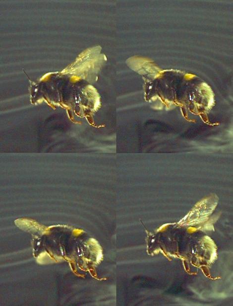

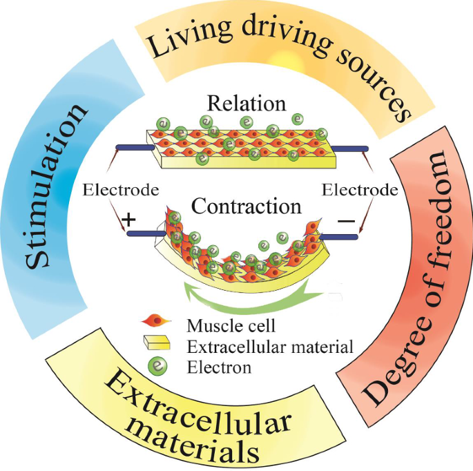

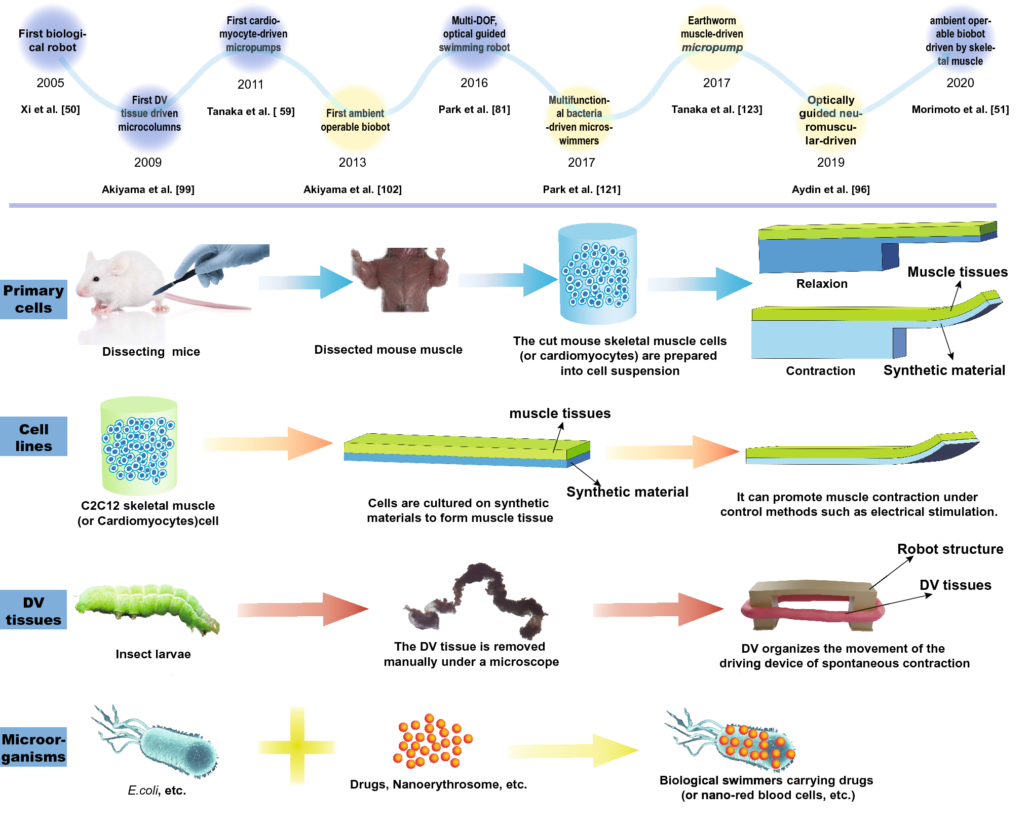
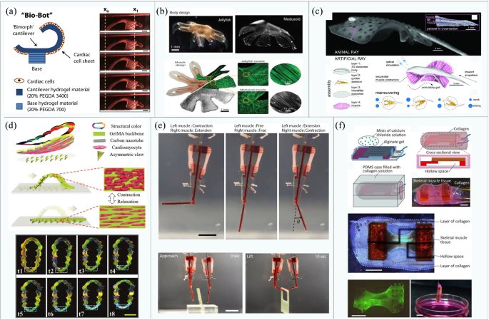
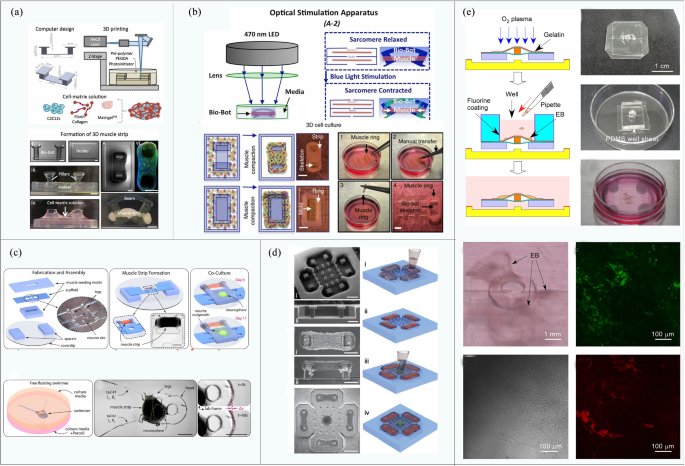
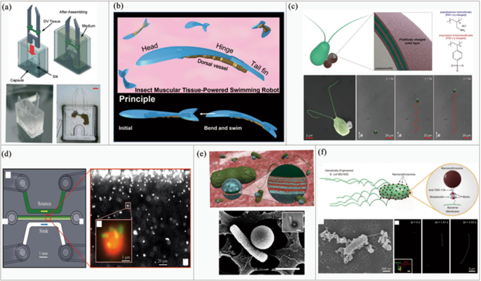
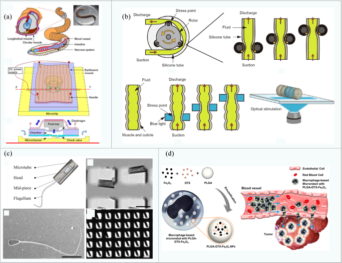
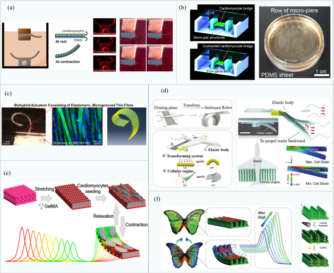
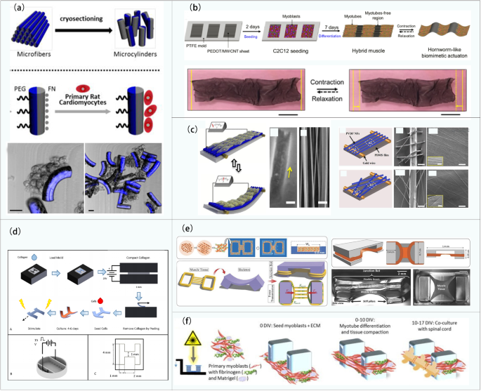
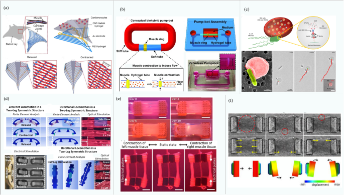


 [
[ 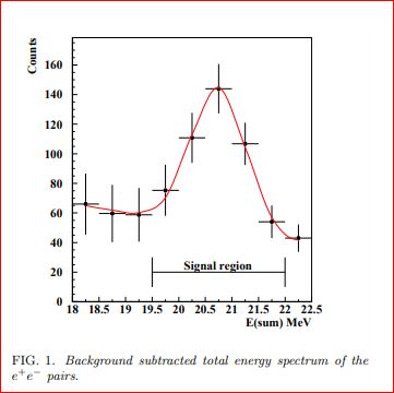 HH
HH 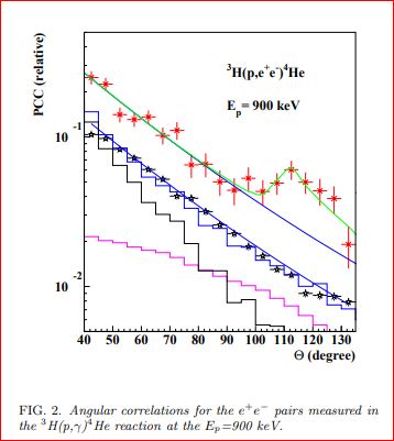 HH
HH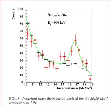 H
H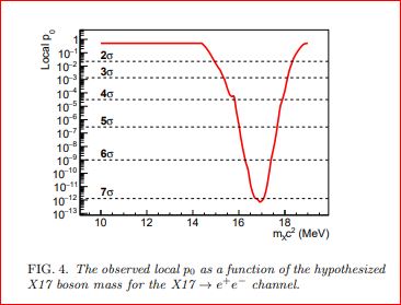 Hhh
Hhh