series
7-10-2022
SOURCE: https://www.loc.gov/item/03006832/ < FROM > United States > Library of Congress
Experimental researches in electricity ( in 3 Volumes ) :
View 638 images in sequence. [ Page view volume 1 ]
View 332 images in sequence. [ Page view volume 2 ]
View 626 images in sequence. [ Page view volume 3 ]
About this Item:
Title: Experimental researches in electricity. Contributor Name : Faraday, Michael, 1791-1867. Created / Published London, R. and J. E. Taylor, 1839-55.
Contents:
volume 1. Series 1-14 [Philosophical transactions, 1832-1838] 1839.--
volume 2. Series 15-18 [Philosophical transactions, 1838-1843. Other electrical papers from Quarterly journal of science and Philosophical magazine] 1844.--
volume 3. Series 19-29 [Philosophical transactions, 1846-1852.
- Other electrical papers from Royal Institution Proceedings and Philosophical magazine] 1855.
https://www.loc.gov/resource/rbctos.2017gen06832v3/?st=gallery&c=160
( https://hansandcassady.org/Faraday-vol3-LOC-page1of4.html )
https://www.loc.gov/resource/rbctos.2017gen06832v3/?c=160&sp=2&st=gallery&r=-0.357,-0.086,1.713,1.713,0 161 - 320
( https://hansandcassady.org/Faraday-vol3-LOC-page2of4.html )
https://www.loc.gov/resource/rbctos.2017gen06832v3/?c=160&sp=3&st=gallery pages 321-480
( https://hansandcassady.org/Faraday-vol3-LOC-page3of4.html )
https://www.loc.gov/resource/rbctos.2017gen06832v3/?c=160&sp=4&st=gallery pages 481 - 626
( https://hansandcassady.org/Faraday-vol3-LOC-page4of4.html )
This eBook is for the use of anyone anywhere at no cost and with
almost no restrictions whatsoever.  You may copy it, give it away or
re-use it under the terms of the Project Gutenberg License included
with this eBook or online at www.gutenberg.org
Title: Experimental Researches in Electricity, Volume 1
Author: Michael Faraday
Release Date: February 9, 2005 [eBook #14986]
[Date last updated: November 5, 2005]
Language: English
Character set encoding: ISO-8859-1
***START OF THE PROJECT GUTENBERG EBOOK EXPERIMENTAL RESEARCHES IN ELECTRICITY, VOLUME 1***
By Michael Faraday, D.C.L. F.R.S.
Fullerian Profesor Of Chemistry In The Royal Institution. Corresponding Member, Etc. Of The Royal And Imperial Academies Of Science Of Paris, Petersburgh, Florence, Copenhagen, Berlin, Gottingen, Modena, Stockholm, Palermo, Etc. Etc.
In Two Volumes.
Vol. I.
Second Edition.
Reprinted from the Philosophical Transactions of 1831-1838.
London: Richard And John Edward Taylor, printers And Publishers To The University Of London, Red Lion Court, Fleet Street. 1849.
I have been induced by various circumstances to collect in One Volume the Fourteen Series of Experimental Researches in Electricity, which have appeared in the Philosophical Transactions during the last seven years: the chief reason has been the desire to supply at a moderate price the whole of these papers, with an Index, to those who may desire to have them.
The readers of the volume will, I hope, do me the justice to remember that it was not written as a whole, but in parts; the earlier portions rarely having any known relation at the time to those which might follow. If I had rewritten the work, I perhaps might have considerably varied the form, but should not have altered much of the real matter: it would not, however, then have been considered a faithful reprint or statement of the course and results of the whole investigation, which only I desired to supply.
I may be allowed to express my great satisfaction at finding, that the different parts, written at intervals during seven years, harmonize so well as they do. There would have been nothing particular in this, if the parts had related only to matters well-ascertained before any of them were written:—but as each professes to contain something of original discovery, or of correction of received views, it does surprise even my partiality, that they should have the degree of consistency and apparent general accuracy which they seem to me to present.
I have made some alterations in the text, but they have been altogether of a typographical or grammatical character; and even where greatest, have been intended to explain the sense, not to alter it. I have often added Notes at the bottom of the page, as to paragraphs 59, 360, 439, 521, 552, 555, 598, 657, 883, for the correction of errors, and also the purpose of illustration: but these are all distinguished from the Original Notes of the Researches by the date of Dec. 1838.
The date of a scientific paper containing any pretensions to discovery is frequently a matter of serious importance, and it is a great misfortune that there are many most valuable communications, essential to the history and progress of science, with respect to which this point cannot now be ascertained. This arises from the circumstance of the papers having no dates attached to them individually, and of the journals in which they appear having such as are inaccurate, i.e. dates of a period earlier than that of publication. I may refer to the note at the end of the First Series, as an illustration of the kind of confusion thus produced. These circumstances have induced me to affix a date at the top of every other page, and I have thought myself justified in using that placed by the Secretary of the Royal Society on each paper as it was received. An author has no right, perhaps, to claim an earlier one, unless it has received confirmation by some public act or officer.
Before concluding these lines I would beg leave to make a reference or two; first, to my own Papers on Electro-magnetic Rotations in the Quarterly Journal of Science, 1822. xii. 74. 186. 283. 416, and also to my Letter on Magneto-electric Induction in the Annales de Chimie, li. p. 404. These might, as to the matter, very properly have appeared in this volume, but they would have interfered with it as a simple reprint of the "Experimental Researches" of the Philosophical Transactions.
Then I wish to refer, in relation to the Fourth Series on a new law of Electric Conduction, to Franklin's experiments on the non-conduction of ice, which have been very properly separated and set forth by Professor Bache (Journal of the Franklin Institute, 1836. xvii. 183.). These, which I did not at all remember as to the extent of the effect, though they in no way anticipate the expression of the law I state as to the general effect of liquefaction on electrolytes, still should never be forgotten when speaking of that law as applicable to the case of water.
There are two papers which I am anxious to refer to, as corrections or criticisms of parts of the Experimental Researches. The first of these is one by Jacobi (Philosophical Magazine, 1838. xiii. 401.), relative to the possible production of a spark on completing the junction of the two metals of a single pair of plates (915.). It is an excellent paper, and though I have not repeated the experiments, the description of them convinces me that I must have been in error. The second is by that excellent philosopher, Marianini (Memoria della Societa Italiana di Modena, xxi. 205), and is a critical and experimental examination of Series viii, and of the question whether metallic contact is or is not productive of a part of the electricity of the voltaic pile. I see no reason as yet to alter the opinion I have given; but the paper is so very valuable, comes to the question so directly, and the point itself is of such great importance, that I intend at the first opportunity renewing the inquiry, and, if I can, rendering the proofs either on the one side or the other undeniable to all.
Other parts of these researches have received the honour of critical attention from various philosophers, to all of whom I am obliged, and some of whose corrections I have acknowledged in the foot notes. There are, no doubt, occasions on which I have not felt the force of the remarks, but time and the progress of science will best settle such cases; and, although I cannot honestly say that I wish to be found in error, yet I do fervently hope that the progress of science in the hands of its many zealous present cultivators will be such, as by giving us new and other developments, and laws more and more general in their applications, will even make me think that what is written and illustrated in these experimental researches, belongs to the by-gone parts of science.
MICHAEL FARADAY.
Royal Institution,
March, 1839.
§ 1. On the Induction of Electric Currents. § 2. On the Evolution of Electricity from Magnetism. § 3. On a new Electrical Condition of Matter. § 4. On Arago's Magnetic Phenomena.
[Read November 24, 1831.]
1. The power which electricity of tension possesses of causing an opposite electrical state in its vicinity has been expressed by the general term Induction; which, as it has been received into scientific language, may also, with propriety, be used in the same general sense to express the power which electrical currents may possess of inducing any particular state upon matter in their immediate neighbourhood, otherwise indifferent. It is with this meaning that I purpose using it in the present paper.
2. Certain effects of the induction of electrical currents have already been recognised and described: as those of magnetization; Ampère's experiments of bringing a copper disc near to a flat spiral; his repetition with electro-magnets of Arago's extraordinary experiments, and perhaps a few others. Still it appeared unlikely that these could be all the effects which induction by currents could produce; especially as, upon dispensing with iron, almost the whole of them disappear, whilst yet an infinity of bodies, exhibiting definite phenomena of induction with electricity of tension, still remain to be acted upon by the induction of electricity in motion.
3. Further: Whether Ampère's beautiful theory were adopted, or any other, or whatever reservation were mentally made, still it appeared very extraordinary, that as every electric current was accompanied by a corresponding intensity of magnetic action at right angles to the current, good conductors of electricity, when placed within the sphere of this action, should not have any current induced through them, or some sensible effect produced equivalent in force to such a current.
4. These considerations, with their consequence, the hope of obtaining electricity from ordinary magnetism, have stimulated me at various times to investigate experimentally the inductive effect of electric currents. I lately arrived at positive results; and not only had my hopes fulfilled, but obtained a key which appeared to me to open out a full explanation of Arago's magnetic phenomena, and also to discover a new state, which may probably have great influence in some of the most important effects of electric currents.
5. These results I purpose describing, not as they were obtained, but in such a manner as to give the most concise view of the whole.
6. About twenty-six feet of copper wire one twentieth of an inch in diameter were wound round a cylinder of wood as a helix, the different spires of which were prevented from touching by a thin interposed twine. This helix was covered with calico, and then a second wire applied in the same manner. In this way twelve helices were superposed, each containing an average length of wire of twenty-seven feet, and all in the same direction. The first, third, fifth, seventh, ninth, and eleventh of these helices were connected at their extremities end to end, so as to form one helix; the others were connected in a similar manner; and thus two principal helices were produced, closely interposed, having the same direction, not touching anywhere, and each containing one hundred and fifty-five feet in length of wire.
7. One of these helices was connected with a galvanometer, the other with a voltaic battery of ten pairs of plates four inches square, with double coppers and well charged; yet not the slightest sensible reflection of the galvanometer-needle could be observed.
8. A similar compound helix, consisting of six lengths of copper and six of soft iron wire, was constructed. The resulting iron helix contained two hundred and fourteen feet of wire, the resulting copper helix two hundred and eight feet; but whether the current from the trough was passed through the copper or the iron helix, no effect upon the other could be perceived at the galvanometer.
9. In these and many similar experiments no difference in action of any kind appeared between iron and other metals.
10. Two hundred and three feet of copper wire in one length were coiled round a large block of wood; other two hundred and three feet of similar wire were interposed as a spiral between the turns of the first coil, and metallic contact everywhere prevented by twine. One of these helices was connected with a galvanometer, and the other with a battery of one hundred pairs of plates four inches square, with double coppers, and well charged. When the contact was made, there was a sudden and very slight effect at the galvanometer, and there was also a similar slight effect when the contact with the battery was broken. But whilst the voltaic current was continuing to pass through the one helix, no galvanometrical appearances nor any effect like induction upon the other helix could be perceived, although the active power of the battery was proved to be great, by its heating the whole of its own helix, and by the brilliancy of the discharge when made through charcoal.
11. Repetition of the experiments with a battery of one hundred and twenty pairs of plates produced no other effects; but it was ascertained, both at this and the former time, that the slight deflection of the needle occurring at the moment of completing the connexion, was always in one direction, and that the equally slight deflection produced when the contact was broken, was in the other direction; and also, that these effects occurred when the first helices were used (6. 8.).
12. The results which I had by this time obtained with magnets led me to believe that the battery current through one wire, did, in reality, induce a similar current through the other wire, but that it continued for an instant only, and partook more of the nature of the electrical wave passed through from the shock of a common Leyden jar than of the current from a voltaic battery, and therefore might magnetise a steel needle, although it scarcely affected the galvanometer.
13. This expectation was confirmed; for on substituting a small hollow helix, formed round a glass tube, for the galvanometer, introducing a steel needle, making contact as before between the battery and the inducing wire (7. 10.), and then removing the needle before the battery contact was broken, it was found magnetised.
14. When the battery contact was first made, then an unmagnetised needle introduced into the small indicating helix (13.), and lastly the battery contact broken, the needle was found magnetised to an equal degree apparently as before; but the poles were of the contrary kind.
15. The same effects took place on using the large compound helices first described (6. 8.).
16. When the unmagnetised needle was put into the indicating helix, before contact of the inducing wire with the battery, and remained there until the contact was broken, it exhibited little or no magnetism; the first effect having been nearly neutralised by the second (13. 14.). The force of the induced current upon making contact was found always to exceed that of the induced current at breaking of contact; and if therefore the contact was made and broken many times in succession, whilst the needle remained in the indicating helix, it at last came out not unmagnetised, but a needle magnetised as if the induced current upon making contact had acted alone on it. This effect may be due to the accumulation (as it is called) at the poles of the unconnected pile, rendering the current upon first making contact more powerful than what it is afterwards, at the moment of breaking contact.
17. If the circuit between the helix or wire under induction and the galvanometer or indicating spiral was not rendered complete before the connexion between the battery and the inducing wire was completed or broken, then no effects were perceived at the galvanometer. Thus, if the battery communications were first made, and then the wire under induction connected with the indicating helix, no magnetising power was there exhibited. But still retaining the latter communications, when those with the battery were broken, a magnet was formed in the helix, but of the second kind (14.), i.e. with poles indicating a current in the same direction to that belonging to the battery current, or to that always induced by that current at its cessation.
18. In the preceding experiments the wires were placed near to each other, and the contact of the inducing one with the buttery made when the inductive effect was required; but as the particular action might be supposed to be exerted only at the moments of making and breaking contact, the induction was produced in another way. Several feet of copper wire were stretched in wide zigzag forms, representing the letter W, on one surface of a broad board; a second wire was stretched in precisely similar forms on a second board, so that when brought near the first, the wires should everywhere touch, except that a sheet of thick paper was interposed. One of these wires was connected with the galvanometer, and the other with a voltaic battery. The first wire was then moved towards the second, and as it approached, the needle was deflected. Being then removed, the needle was deflected in the opposite direction. By first making the wires approach and then recede, simultaneously with the vibrations of the needle, the latter soon became very extensive; but when the wires ceased to move from or towards each other, the galvanometer-needle soon came to its usual position.
19. As the wires approximated, the induced current was in the contrary direction to the inducing current. As the wires receded, the induced current was in the same direction as the inducing current. When the wires remained stationary, there was no induced current (54.).
20. When a small voltaic arrangement was introduced into the circuit between the galvanometer (10.) and its helix or wire, so as to cause a permanent deflection of 30° or 40°, and then the battery of one hundred pairs of plates connected with the inducing wire, there was an instantaneous action as before (11.); but the galvanometer-needle immediately resumed and retained its place unaltered, notwithstanding the continued contact of the inducing wire with the trough: such was the case in whichever way the contacts were made (33.).
21. Hence it would appear that collateral currents, either in the same or in opposite directions, exert no permanent inducing power on each other, affecting their quantity or tension.
22. I could obtain no evidence by the tongue, by spark, or by heating fine wire or charcoal, of the electricity passing through the wire under induction; neither could I obtain any chemical effects, though the contacts with metallic and other solutions were made and broken alternately with those of the battery, so that the second effect of induction should not oppose or neutralise the first (13. 16.).
23. This deficiency of effect is not because the induced current of electricity cannot pass fluids, but probably because of its brief duration and feeble intensity; for on introducing two large copper plates into the circuit on the induced side (20.), the plates being immersed in brine, but prevented from touching each other by an interposed cloth, the effect at the indicating galvanometer, or helix, occurred as before. The induced electricity could also pass through a voltaic trough (20.). When, however, the quantity of interposed fluid was reduced to a drop, the galvanometer gave no indication.
24. Attempts to obtain similar effects by the use of wires conveying ordinary electricity were doubtful in the results. A compound helix similar to that already described, containing eight elementary helices (6.), was used. Four of the helices had their similar ends bound together by wire, and the two general terminations thus produced connected with the small magnetising helix containing an unmagnetised needle (13.). The other four helices were similarly arranged, but their ends connected with a Leyden jar. On passing the discharge, the needle was found to be a magnet; but it appeared probable that a part of the electricity of the jar had passed off to the small helix, and so magnetised the needle. There was indeed no reason to expect that the electricity of a jar possessing as it does great tension, would not diffuse itself through all the metallic matter interposed between the coatings.
25. Still it does not follow that the discharge of ordinary electricity through a wire does not produce analogous phenomena to those arising from voltaic electricity; but as it appears impossible to separate the effects produced at the moment when the discharge begins to pass, from the equal and contrary effects produced when it ceases to pass (16.), inasmuch as with ordinary electricity these periods are simultaneous, so there can be scarcely any hope that in this form of the experiment they can be perceived.
26. Hence it is evident that currents of voltaic electricity present phenomena of induction somewhat analogous to those produced by electricity of tension, although, as will be seen hereafter, many differences exist between them. The result is the production of other currents, (but which are only momentary,) parallel, or tending to parallelism, with the inducing current. By reference to the poles of the needle formed in the indicating helix (13. 14.) and to the deflections of the galvanometer-needle (11.), it was found in all cases that the induced current, produced by the first action of the inducing current, was in the contrary direction to the latter, but that the current produced by the cessation of the inducing current was in the same direction (19.). For the purpose of avoiding periphrasis, I propose to call this action of the current from the voltaic battery, volta-electric induction. The properties of the second wire, after induction has developed the first current, and whilst the electricity from the battery continues to flow through its inducing neighbour (10. 18.), constitute a peculiar electric condition, the consideration of which will be resumed hereafter (60.). All these results have been obtained with a voltaic apparatus consisting of a single pair of plates.
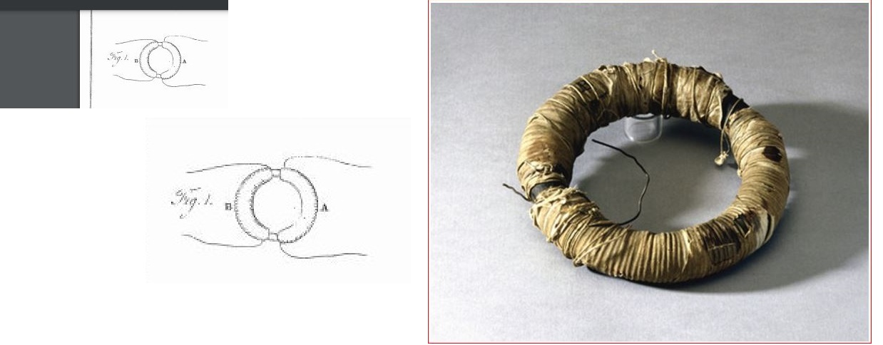
§ 2. "Evolution of Electricity from Magnetism." "fig. 1"
fARADAY-Series-First-fig-01.jpg
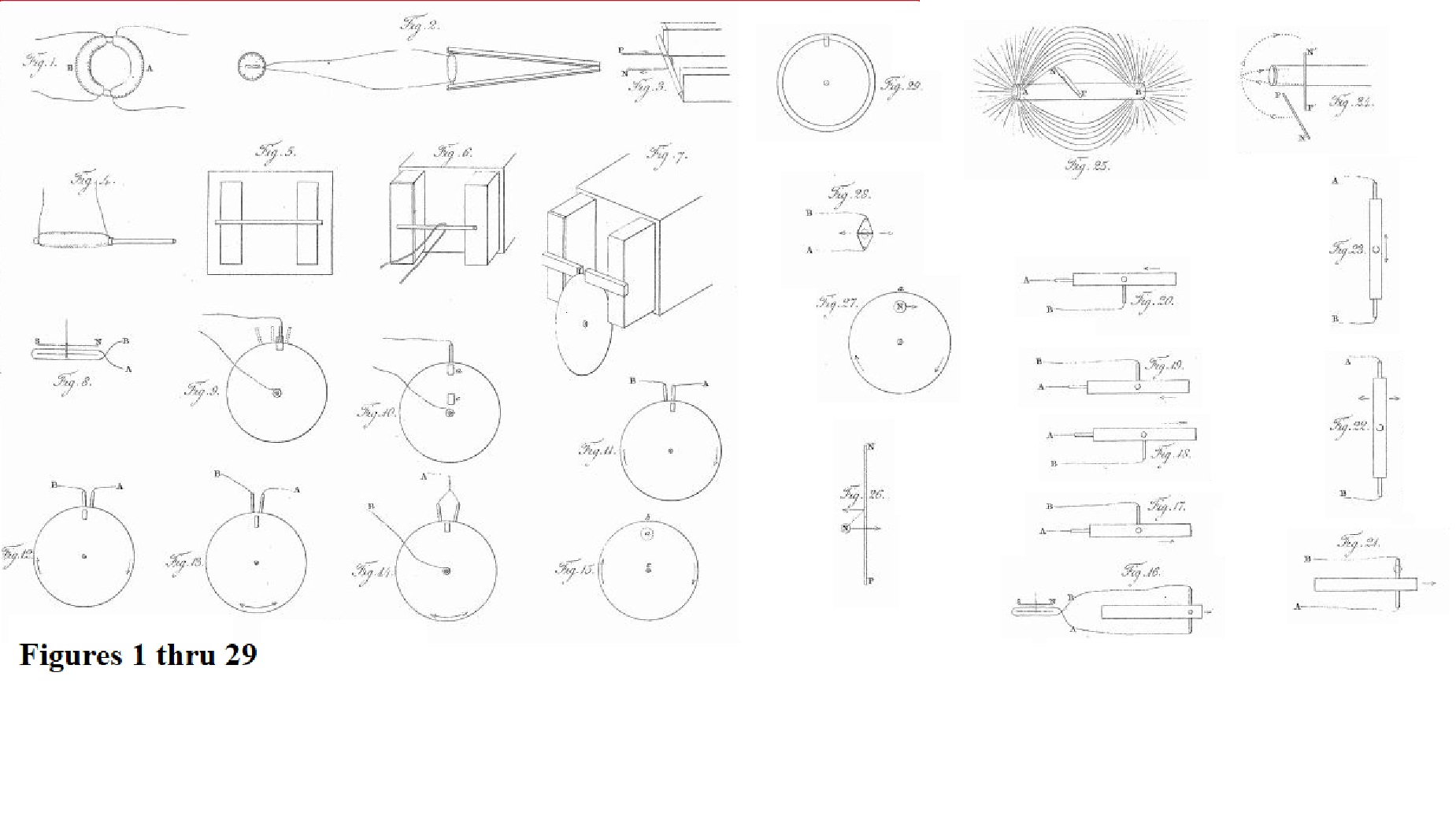
27. A welded ring was made of soft round bar-iron, the metal being seven-eighths of an inch in thickness, and the ring six inches in external diameter. Three helices were put round one part of this ring, each containing about twenty-four feet of copper wire one twentieth of an inch thick; they were insulated from the iron and each other, and superposed in the manner before described (6.), occupying about nine inches in length upon the ring. They could be used separately or conjointly; the group may be distinguished by the letter A (Pl. I. fig. 1.). On the other part of the ring about sixty feet of similar copper wire in two pieces were applied in the same manner, forming a helix B, which had the same common direction with the helices of A, but being separated from it at each extremity by about half an inch of the uncovered iron.
paragraph 28 29, 30 > https://www.loc.gov/resource/rbctos.2017gen06832v1/?sp=20
31, 32, 33, 34, 35, https://tile.loc.gov/storage-services/service/rbc/rbctos/2017gen06832v1/2017gen06832v1.pdf YES!
https://www.loc.gov/resource/rbctos.2017gen06832v1/?sp=19 ( Image 19 of Page view volume 1 Page view volume 1
https://www.loc.gov/resource/rbctos.2017gen06832v1/?sp=20
36. Similar effects were then produced by ordinary magnets: thus the hollow helix just described (34.) had all its elementary helices connected with the galvanometer by two copper wires, each five feet in length; the soft iron cylinder was introduced into its axis; a couple of bar magnets, each twenty-four inches long, were arranged with their opposite poles at one end in contact, so as to resemble a horse-shoe magnet, and then contact made between the other poles and the ends of the iron cylinder, so as to convert it for the time into a magnet (fig. 2.): by breaking the magnetic contacts, or reversing them, the magnetism of the iron cylinder could be destroyed or reversed at pleasure.
37.
38. When the magnetic contact was made, the deflection was such as to indicate an induced current of electricity in the opposite direction to that fitted to form a magnet, having the same polarity as that really produced by contact with the bar magnets. Thus when the marked and unmarked poles were placed as in fig. 3, the current in the helix was in the direction represented, P being supposed to be the end of the wire going to the positive pole of the battery, or that end towards which the zinc plates face, and N the negative wire. Such a current would have converted the cylinder into a magnet of the opposite kind to that formed by contact with the poles A and B; and such a current moves in the opposite direction to the currents which in M. Ampère's beautiful theory are considered as constituting a magnet in the position figured1.
39. But as it might be supposed that in all the preceding experiments of this section, it was by some peculiar effect taking place during the formation of the magnet, and not by its mere virtual approximation, that the momentary induced current was excited, the following experiment was made. All the similar ends of the compound hollow helix (34.) were bound together by copper wire, forming two general terminations, and these were connected with the galvanometer. The soft iron cylinder (34.) was removed, and a cylindrical magnet, three quarters of an inch in diameter and eight inches and a half in length, used instead. One end of this magnet was introduced into the axis of the helix (fig. 4.), and then, the galvanometer-needle being stationary, the magnet was suddenly thrust in; immediately the needle was deflected in the same direction as if the magnet had been formed by either of the two preceding processes (34. 36.). Being left in, the needle resumed its first position, and then the magnet being withdrawn the needle was deflected in the opposite direction. These effects were not great; but by introducing and withdrawing the magnet, so that the impulse each time should be added to those previously communicated to the needle, the latter could be made to vibrate through an arc of 180° or more.
40. 41. 42. 43.
44. The Royal Society are in possession of a large compound magnet formerly belonging to Dr. Gowin Knight, which, by permission of the President and Council, I was allowed to use in the prosecution of these experiments: it is at present in the charge of Mr. Christie, at his house at Woolwich, where, by Mr. Christie's kindness, I was at liberty to work; and I have to acknowledge my obligations to him for his assistance in all the experiments and observations made with it. This magnet is composed of about 450 bar magnets, each fifteen inches long, one inch wide, and half an inch thick, arranged in a box so as to present at one of its extremities two external poles (fig. 5.). These poles projected horizontally six inches from the box, were each twelve inches high and three inches wide. They were nine inches apart; and when a soft iron cylinder, three quarters of an inch in diameter and twelve inches long, was put across from one to the other, it required a force of nearly one hundred pounds to break the contact. The pole to the left in the figure is the marked pole2.
45. 46. 47. 48.
49. Dismissing the helices and sockets, the galvanometer wire was passed over, and consequently only half round the iron cylinder (fig. 6.); but even then a strong effect upon the needle was exhibited, when the magnetic contact was made or broken.
49. thru 83.
84. The magnet has been already described (44.). To concentrate the poles, and bring them nearer to each other, two iron or steel bars, each about six or seven inches long, one inch wide, and half an inch thick, were put across the poles as in fig. 7, and being supported by twine from slipping, could be placed as near to or far from each other as was required. Occasionally two bars of soft iron were employed, so bent that when applied, one to each pole, the two smaller resulting poles were vertically over each other, either being uppermost at pleasure.
85. 86.
87. The galvanometer was roughly made, yet sufficiently delicate in its indications. The wire was of copper covered with silk, and made sixteen or eighteen convolutions. Two sewing-needles were magnetized and fixed on to a stem of dried grass parallel to each other, but in opposite directions, and about half an inch apart; this system was suspended by a fibre of unspun silk, so that the lower needle should be between the convolutions of the multiplier, and the upper above them. The latter was by much the most powerful magnet, and gave terrestrial direction to the whole; fig. 8. represents the direction of the wire and of the needles when the instrument was placed in the magnetic meridian: the ends of the wires are marked A and B for convenient reference hereafter. The letters S and N designate the south and north ends of the needle when affected merely by terrestrial magnetism; the end N is therefore the marked pole (44.). The whole instrument was protected by a glass jar, and stood, as to position and distance relative to the large magnet, under the same circumstances as before (45.).
88. 89. 90. 91.
92. When the conductor was placed on the edge of the disc a little to the right or left, as in the dotted positions fig. 9, the current of electricity was still evolved, and in the same direction as at first (88.
93. On raising the plate, so that the magnetic poles were entirely hidden from each other by its intervention, (a. fig. 10,) the same effects were produced in the same order, and with equal intensity as before. On raising it still higher, so as to bring the place of the poles to c, still the effects were produced, and apparently with as much power as at first.
94.
95. When the galvanometer connexion with the axis was broken, and its wires made fast to two conductors, both applied to the edge of the copper disc, then currents of electricity were produced, presenting more complicated appearances, but in perfect harmony with the above results. Thus, if applied as in fig. 11, a current of electricity through the galvanometer was produced; but if their place was a little shifted, as in fig. 12, a current in the contrary direction resulted; the fact being, that in the first instance the galvanometer indicated the difference between a strong current through A and a weak one through B, and in the second, of a weak current through A and a strong one through B (92.), and therefore produced opposite deflections.
96. So also when the two conductors were equidistant from the magnetic poles, as in fig. 13, no current at the galvanometer was perceived, whichever way the disc was rotated, beyond what was momentarily produced by irregularity of contact; because equal currents in the same direction tended to pass into both. But when the two conductors were connected with one wire, and the axis with the other wire, (fig. 14,) then the galvanometer showed a current according with the direction of rotation (91.); both conductors now acting consentaneously, and as a single conductor did before (88.).
97. 98.
99. The relation of the current of electricity produced, to the magnetic pole, to the direction of rotation of the plate, &c. &c., may be expressed by saying, that when the unmarked pole (44. 84.) is beneath the edge of the plate, and the latter revolves horizontally, screw-fashion, the electricity which can be collected at the edge of the plate nearest to the pole is positive. As the pole of the earth may mentally be considered the unmarked pole, this relation of the rotation, the pole, and the electricity evolved, is not difficult to remember. Or if, in fig. 15, the circle represent the copper disc revolving in the direction of the arrows, and a the outline of the unmarked pole placed beneath the plate, then the electricity collected at b and the neighbouring parts is positive, whilst that collected at the centre c and other parts is negative (88.). The currents in the plate are therefore from the centre by the magnetic poles towards the circumference.
100.
101. It is now evident that the rotating plate is merely another form of the simpler experiment of passing a piece of metal between the magnetic poles in a rectilinear direction, and that in such cases currents of electricity are produced at right angles to the direction of the motion, and crossing it at the place of the magnetic pole or poles. This was sufficiently shown by the following simple experiment: A piece of copper plate one fifth of an inch thick, one inch and a half wide, and twelve inches long, being amalgamated at the edges, was placed between the magnetic poles, whilst the two conductors from the galvanometer were held in contact with its edges; it was then drawn through between the poles of the conductors in the direction of the arrow, fig. 16; immediately the galvanometer needle was deflected, its north or marked end passed eastward, indicating that the wire A received negative and the wire B positive electricity; and as the marked pole was above, the result is in perfect accordance with the effect obtained by the rotatory plate (99.).
102.
103. To render evident the character of the electrical current existing in various parts of the moving copper plate, differing in their relation to the inducing poles, one collector (86.) only was applied at the part to be examined near to the pole, the other being connected with the end of the plate as the most neutral place: the results are given at fig. 17-20, the marked pole being above the plate. In fig. 17, B received positive electricity; but the plate moving in the same direction, it received on the opposite side, fig. 18, negative electricity: reversing the motion of the latter, as in fig. 20, B received positive electricity; or reversing the motion of the first arrangement, that of fig. 17 to fig. 19, B received negative electricity.
104. When the plates were previously removed sideways from between the magnets, as in fig. 21, so as to be quite out of the polar axis, still the same effects were produced, though not so strongly.
105. 106. 107.
108. On the conductors being held against the ends of the plates, and the latter then passed between the magnetic poles, in a direction transverse to their length, the same effects were produced (fig. 22.). The parts of the plates towards the end may be considered either as mere conductors, or as portions of metal in which the electrical current is excited, according to their distance and the strength of the magnet; but the results were in perfect harmony with those before obtained. The effect was as strong as when the conductors were held against the sides of the plate (101.).
109.
110. Upon connecting the ends of a plate of metal with the galvanometer wires, and then carrying it between the poles from end to end (as in fig. 23.), in either direction, no effect whatever was produced upon the galvanometer. But the moment the motion became transverse, the needle was deflected.
111. 112. 113.
114. The relation which holds between the magnetic pole, the moving wire or metal, and the direction of the current evolved, i.e. the law which governs the evolution of electricity by magneto-electric induction, is very simple, although rather difficult to express. If in fig. 24, PN represent a horizontal wire passing by a marked magnetic pole, so that the direction of its motion shall coincide with the curved line proceeding from below upwards; or if its motion parallel to itself be in a line tangential to the curved line, but in the general direction of the arrows; or if it pass the pole in other directions, but so as to cut the magnetic curves13 in the same general direction, or on the same side as they would be cut by the wire if moving along the dotted curved line;—then the current of electricity in the wire is from P to N. If it be carried in the reverse directions, the electric current will be from N to P. Or if the wire be in the vertical position, figured P' N', and it be carried in similar directions, coinciding with the dotted horizontal curve so far, as to cut the magnetic curves on the same side with it, the current will be from P' to N'. If the wire be considered a tangent to the curved surface of the cylindrical magnet, and it be carried round that surface into any other position, or if the magnet itself be revolved on its axis, so as to bring any part opposite to the tangential wire,—still, if afterwards the wire be moved in the directions indicated, the current of electricity will be from P to N; or if it be moved in the opposite direction, from N to P; so that as regards the motions of the wire past the pole, they may be reduced to two, directly opposite to each other, one of which produces a current from P to N, and the other from N to P.
115.
116. Hence the current of electricity which is excited in metal when moving in the neighbourhood of a magnet, depends for its direction altogether upon the relation of the metal to the resultant of magnetic action, or to the magnetic curves, and may be expressed in a popular way thus; Let AB (fig. 25.) represent a cylinder magnet, A being the marked pole, and B the unmarked pole; let PN be a silver knife-blade, resting across the magnet with its edge upward, and with its marked or notched side towards the pole A; then in whatever direction or position this knife be moved edge foremost, either about the marked or the unmarked pole, the current of electricity produced will be from P to N, provided the intersected curves proceeding from A abut upon the notched surface of the knife, and those from B upon the unnotched side. Or if the knife be moved with its back foremost, the current will be from N to P in every possible position and direction, provided the intersected curves abut on the same surfaces as before. A little model is easily constructed, by using a cylinder of wood for a magnet, a flat piece for the blade, and a piece of thread connecting one end of the cylinder with the other, and passing through a hole in the blade, for the magnetic curves: this readily gives the result of any possible direction.
117. 118. 119. 120.
121. The effect is precisely of the same kind as the electromagnetic rotations which I had the good fortune to discover some years ago14. According to the experiments then made which have since been abundantly confirmed, if a wire (PN fig. 26.) be connected with the positive and negative ends of a voltaic buttery, so that the positive electricity shall pass from P to N, and a marked magnetic pole N be placed near the wire between it and the spectator, the pole will move in a direction tangential to the wire, i.e. towards the right, and the wire will move tangentially towards the left, according to the directions of the arrows. This is exactly what takes place in the rotation of a plate beneath a magnetic pole; for let N (fig. 27.) be a marked pole above the circular plate, the latter being rotated in the direction of the arrow: immediately currents of positive electricity set from the central parts in the general direction of the radii by the pole to the parts of the circumference a on the other side of that pole (99. 119.), and are therefore exactly in the same relation to it as the current in the wire (PN, fig. 26.), and therefore the pole in the same manner moves to the right hand.
122. 123. 124. 125. 126.
127. All the effects of solution of metallic continuity, and the consequent diminution of power described by Messrs. Babbage and Herschel15, now receive their natural explanation, as well also as the resumption of power when the cuts were filled up by metallic substances, which, though conductors of electricity, were themselves very deficient in the power of influencing magnets. And new modes of cutting the plate may be devised, which shall almost entirely destroy its power. Thus, if a copper plate (81.) be cut through at about a fifth or sixth of its diameter from the edge, so as to separate a ring from it, and this ring be again fastened on, but with a thickness of paper intervening (fig. 29.), and if Arago's experiment be made with this compound plate so adjusted that the section shall continually travel opposite the pole, it is evident that the magnetic currents will be greatly interfered with, and the plate probably lose much of its effect16.
128. thru 170.
An elementary result of this kind was obtained by using two pieces of thick copper, shaped as in fig. 28. When the two neighbouring edges were amalgamated and put together, and the arrangement passed between the poles of the magnet, in the direction parallel to these edges, a current was urged through the wires attached to the outer angles, and the galvanometer became strongly affected; but when a single film of paper was interposed, and the experiment repeated, no sensible effect could be produced.
171. A piece of common copper wire, about eight feet long and one twentieth of an inch in thickness, had one of its ends fastened to one of the terminations of the galvanometer wire, and the other end to the other termination; thus it formed an endless continuation of the galvanometer wire: it was then roughly adjusted into the shape of a rectangle, or rather of a loop, the upper part of which could be carried to and fro over the galvanometer, whilst the lower part, and the galvanometer attached to it, remained steady (Plate II. fig. 30.). Upon moving this loop over the galvanometer from right to left, the magnetic needle was immediately deflected; upon passing the loop back again, the needle passed in the contrary direction to what it did before; upon repeating these motions of the loop in accordance with the vibrations of the needle (39.), the latter soon swung through 90° or more.
172. 173. 174. 175.
176. If in fig. 31 dp be parallel to the dip, and BA be considered as the upper part of the rectangle (171.), with an arrow c attached to it, both these being retained in a plane perpendicular to the dip,—then, however BA with its attached arrow is moved upon dp as an axis, if it afterwards proceed in the direction of the arrow, a current of electricity will move along it from B towards A.
195. The twisted copper and iron (touching each other nowhere but at the extremity) were then passed between the poles of a powerful magnet arranged horse-shoe fashion (fig. 32.); but not the slightest effect was observed at the galvanometer, although the arrangement seemed fitted to show any electrical difference between the two metals relative to the action of the magnet,
196. thru 207.
208. I then had wires of iron, zinc, copper, tin, and lead, drawn to the same diameter (very nearly one twentieth of an inch), and I compared exactly equal lengths, namely sixteen feet, of each in pairs in the following manner: The ends of the copper wire were connected with the ends A and B of galvanometer coil K, and the ends of the zinc wire with the terminations A and B of the galvanometer coil L. The middle part of each wire was then coiled six times round a cylinder of soft iron covered with paper, long enough to connect the poles of Daniell's horse-shoe magnet (56.) (fig. 33.), so that similar helices of copper and zinc, each of six turns, surrounded the bar at two places equidistant from each other and from the poles of the magnet; but these helices were purposely arranged so as to be in contrary directions, and therefore send contrary currents through the galvanometer coils K and L,
225. A cylinder magnet, seven inches in length, and three quarters of an inch in diameter, had a hole pierced in the direction of its axis from one extremity, a quarter of an inch in diameter, and three inches deep. A copper cylinder, surrounded by paper and amalgamated at both extremities, was introduced so as to be in metallic contact at the bottom of the hole, by a little mercury, with the middle of the magnet; insulated at the sides by the paper; and projecting about a quarter of an inch above the end of the steel. A quill was put over the copper rod, which reached to the paper, and formed a cup to receive mercury for the completion of the circuit. A high paper edge was also raised round that end of the magnet and mercury put within it, which however had no metallic connexion with that in the quill, except through the magnet itself and the copper rod (fig. 34.). The wires A and B from the galvanometer were dipped into these two portions of mercury; any current through them could, therefore, only pass down the magnet towards its equatorial parts, and then up the copper rod; or vice versa.
226.
227. The magnet was then put into a jar of mercury (fig. 35.) as before (219.); the wire A left in contact with the copper axis, but the wire B dipped in the mercury of the jar, and therefore in metallic communication with the equatorial parts of the magnet instead of its polar extremity. On revolving the magnet screw fashion, the galvanometer needle was deflected in the same direction as before, but far more powerfully. Yet it is evident that the parts of the magnet from the equator to the pole were out of the electric circuit.
228. Then the wire A was connected with the mercury on the extremity of the magnet, the wire B still remaining in contact with that in the jar (fig. 36.), so that the copper axis was altogether out of the circuit. The magnet was again revolved screw fashion, and again caused the same deflection of the needle, the current being as strong as it was in the last trial (227.), and much stronger than at first (226.).
figures 37, 38, 39
233. If the wire NP (fig. 40.) have an electric current passed through it in the direction from P to N, then the dotted ring may represent a magnetic curve round it, and it is in such a direction that if small magnetic needles lie placed as tangents to it, they will become arranged as in the figure, n and s indicating north and south ends (14. note.).
234. But if the current of electricity were made to cease for a while, and magnetic poles were used instead to give direction to the needles, and make them take the same position as when under the influence of the current, then they must be arranged as at fig. 41; the marked and unmarked poles ab above the wire, being in opposite directions to those a'b' below. In such a position therefore the magnetic curves between the poles ab and a'b' have the same general direction with the corresponding parts of the ring magnetic curve surrounding the wire NP carrying an electric current.
figures 42, 43, 44, 45
271. As heated air discharges common electricity with far greater facility than points, I hoped that voltaic electricity might in this way also be discharged. An apparatus was therefore constructed (Plate III. fig. 46.), in which AB is an insulated glass rod upon which two copper wires, C, D, are fixed firmly; to these wires are soldered two pieces of fine platina wire, the ends of which are brought very close to each other at e, but without touching; the copper wire C was connected with the positive pole of a voltaic battery, and the wire D with a decomposing apparatus (312. 316.), from which the communication was completed to the negative pole of the battery. In these experiments only two troughs, or twenty pairs of plates, were used.
462. A piece of turmeric paper, not more than 0.4 of an inch in length and 0.5 of an inch in width, was moistened with sulphate of soda and placed upon the edge of a glass plate opposite to, and about two inches from, a point connected with the discharging train (Plate IV. fig. 47.); a piece of tinfoil, resting upon the same glass plate, was connected with the machine, and also with the turmeric paper, by a decomposing wire a (312.). The machine was then worked, the positive electricity passing into the turmeric paper at the point p, and out at the extremity n. After forty or fifty turns of the machine, the extremity n was examined, and the two points or angles found deeply coloured by the presence of free alkali (fig. 48.).
463. A similar piece of litmus paper, dipped in solution of sulphate of soda n, fig. 49, was now supported upon the end of the discharging train a, and its extremity brought opposite to a point p, connected with the conductor of the machine. After working the machine for a short time, acid was developed at both the corners towards the point, i.e. at both the corners receiving the electricities from the air. Every precaution was taken to prevent this acid from being formed by sparks or brushes passing through the air (322.); and these, with the accompanying general facts, are sufficient to show that the acid was really the result of electro-chemical decomposition (466.).
464. Then a long piece of turmeric paper, large at one end and pointed at the other, was moistened in the saline solution, and immediately connected with the conductor of the machine, so that its pointed extremity was opposite a point upon the discharging train. When the machine was worked, alkali was evolved at that point; and even when the discharging train was removed, and the electricity left to be diffused and carried off altogether by the air, still alkali was evolved where the electricity left the turmeric paper.
465. Arrangements were then made in which no metallic communication with the decomposing matter was allowed, but both poles (if they might now be called by that name) formed of air only. A piece of turmeric paper a fig. 50, and a piece of litmus paper b, were dipped in solution of sulphate of soda, put together so as to form one moist pointed conductor, and supported on wax between two needle points, one, p, connected by a wire with the conductor of the machine, and the other, n, with the discharging train. The interval in each case between the points was about half an inch; the positive point p was opposite the litmus paper; the negative point n opposite the turmeric. The machine was then worked for a time, upon which evidence of decomposition quickly appeared, for the point of the litmus b became reddened from acid evolved there, and the point of the turmeric a red from a similar and simultaneous evolution of alkali.
469. Finally, a series of four small compound conductors, consisting of litmus and turmeric paper (fig. 51.) moistened in solution of sulphate of soda, were supported on glass rods, in a line at a little distance from each other, between the points p and n of the machine and discharging train, so that the electricity might pass in succession through them, entering in at the litmus points b, b, and passing out at the turmeric points a, a. On working the machine carefully, so as to avoid sparks and brushes (322.), I soon obtained evidence of decomposition in each of the moist conductors, for all the litmus points exhibited free acid, and the turmeric points equally showed free alkali.
494. A glass basin (fig. 52.), four inches in diameter and four inches deep, had a division of mica a, fixed across the upper part so as to descend one inch and a half below the edge, and be perfectly water-tight at the sides: a plate of platina b, three inches wide, was put into the basin on one side of the division a, and retained there by a glass block below, so that any gas produced by it in a future stage of the experiment should not ascend beyond the mica, and cause currents in the liquid on that side. A strong solution of sulphate of magnesia was carefully poured without splashing into the basin, until it rose a little above the lower edge of the mica division a, great care being taken that the glass or mica on the unoccupied or c side of the division in the figure, should not be moistened by agitation of the solution above the level to which it rose. A thin piece of clean cork, well-wetted in distilled water, was then carefully and lightly placed on the solution at the c side, and distilled water poured gently on to it until a stratum the eighth of an inch in thickness appeared over the sulphate of magnesia; all was then left for a few minutes, that any solution adhering to the cork might sink away from it, or be removed by the water on which it now floated; and then more distilled water was added in a similar manner, until it reached nearly to the top of the glass. In this way solution of the sulphate occupied the lower part of the glass, and also the upper on the right-hand side of the mica; but on the left-hand side of the division a stratum of water from c to d, one inch and a half in depth, reposed upon it, the two presenting, when looked through horizontally, a comparatively definite plane of contact. A second platina pole e, was arranged so as to be just under the surface of the water, in a position nearly horizontal, a little inclination being given to it, that gas evolved during decomposition might escape: the part immersed was three inches and a half long by one inch wide, and about seven-eighths of an inch of water intervened between it and the solution of sulphate of magnesia.
519. In this view the effect is considered as essentially dependent upon the mutual chemical affinity of the particles of opposite kinds. Particles aa, fig. 53, could not be transferred or travel from one pole N towards the other P, unless they found particles of the opposite kind bb, ready to pass in the contrary direction: for it is by virtue of their increased affinity for those particles, combined with their diminished affinity for such as are behind them in their course, that they are urged forward: and when any one particle a, fig. 54, arrives at the pole, it is excluded or set free, because the particle b of the opposite kind, with which it was the moment before in combination, has, under the superinducing influence of the current, a greater attraction for the particle a', which is before it in its course, than for the particle a, towards which its affinity has been weakened.
520. As far as regards any single compound particle, the case may be considered as analogous to one of ordinary decomposition, for in fig. 54, a may be conceived to be expelled from the compound ab by the superior attraction of a' for b, that superior attraction belonging to it in consequence of the relative position of a'b and a to the direction of the axis of electric power (517.) superinduced by the current. But as all the compound particles in the course of the current, except those actually in contact with the poles, act conjointly, and consist of elementary particles, which, whilst they are in one direction expelling, are in the other being expelled, the case becomes more complicated, but not more difficult of comprehension.
526. Four glass cups were then arranged, as in fig. 55; seventeen measures of the free sulphuric acid (525.) were put into each of the vessels a and b, and seventeen measures of the solution of sulphate of soda into each of the vessels A and B. Asbestus, which had been well-washed in acid, acted upon by the voltaic pile, well-washed in water, and dried by pressure, was used to connect a with b and A with B, the portions being as equal as they could be made in quantity, and cut as short as was consistent with their performing the part of effectual communications, b and A were connected by two platina plates or poles soldered to the extremities of one wire, and the cups a and B were by similar platina plates connected with a voltaic battery of forty pairs of plates four inches square, that in a being connected with the negative, and that in B with the positive pole. The battery, which was not powerfully charged, was retained in communication above half an hour. In this manner it was certain that the same electric current had passed through a b and A B, and that in each instance the same quantity and strength of acid had been submitted to its action, but in one case merely dissolved in water, and in the other dissolved and also combined with an alkali.
566. During the course of the experiments made to render the instrument efficient, I was occasionally surprised at observing a deficiency of the gases resulting from the decompositions of water, and at last an actual disappearance of portions which had been evolved, collected, and measured. The circumstances of the disappearance were these. A glass tube, about twelve inches in length and 3/4ths of an inch in diameter, had two platina poles fixed into its upper, hermetically sealed, extremity: the poles, where they passed through the glass, were of wire; but terminated below in plates, which were soldered to the wires with gold (Plate V. fig. 56.). The tube was filled with dilute sulphuric acid, and inverted in a cup of the same fluid; a voltaic battery was connected with the two wires, and sufficient oxygen and hydrogen evolved to occupy 4/5ths of the tube, or by the graduation, 116 parts. On separating the tube from the voltaic battery the volume of gas immediately began to diminish, and in about five hours only 13-1/2 parts remained, and these ultimately disappeared.
569. Several platina plates were prepared (fig. 57.). They were nearly half an inch wide, and two inches and a half long: some were 1/200dth of an inch, others not more than 1/600dth, whilst some were as much as 1/70th of an inch in thickness. Each had a piece of platina wire, about seven inches long, soldered to it by pure gold. Then a number of glass tubes were prepared: they were about nine or ten inches in length, 5/8ths of an inch in internal diameter, were sealed hermetically at one extremity, and were graduated. Into these tubes was put a mixture of two volumes of hydrogen and one of oxygen, at the water pneumatic trough, and when one of the plates described had been connected with the positive or negative pole of the voltaic battery for a given time, or had been otherwise prepared, it was introduced through the water into the gas within the tube; the whole set aside in a test-glass (fig. 58.), and left for a longer or shorter period, that the action might be observed.
609. There can remain no doubt that the property of inducing combination, which can thus be conferred upon masses of platina and other metals by connecting them with the poles of the battery, or by cleansing processes either of a mechanical or chemical nature, is the same as that which was discovered by Döbereiner136, in 1823, to belong in so eminent a degree to spongy platina, and which was afterwards so well experimented upon and illustrated by MM. Dulong and Thenard137, in 1823. The latter philosophers even quote experiments in which a very fine platina wire, which had been coiled up and digested in nitric, sulphuric, or muriatic acid, became ignited when put into a jet of hydrogen gas138. This effect I can now produce at pleasure with either wires or plates by the processes described (570. 601. 605.); and by using a smaller plate cut so that it shall rest against the glass by a few points, and yet allow the water to flow off (fig. 59.), the loss of heat is less, the metal is assimilated somewhat to the spongy state, and the probability of failure almost entirely removed.
figures 60. 61, 62, 63, 64, 65, 66, 67
600. With regard to the exceptions (679.), upon closer examination some of them disappear. Chloride of antimony (a compound of one proportional of antimony and one and a half of chlorine) of recent preparation was put into a tube (fig. 68.) (789.), and submitted when fused to the action of the current, the positive electrode being of plumbago. No electricity passed, and no appearance of decomposition was visible at first; but when the positive and negative electrodes were brought very near each other in the chloride, then a feeble action occurred and a feeble current passed. The effect altogether was so small (although quite amenable to the law before given (394.)), and so unlike the decomposition and conduction occurring in all the other cases, that I attribute it to the presence of a minute quantity of water, (for which this and many other chlorides have strong attractions, producing hydrated chlorides,) or perhaps of a true protochloride consisting of single proportionals (695, 796.).
************
707. The first precaution needful in the construction of the instrument was to avoid the recombination of the evolved gases, an effect which the positive electrode has been found so capable of producing (571.). For this purpose various forms of decomposing apparatus were used. The first consisted of straight tubes, each containing a plate and wire of platina soldered together by gold, and fixed hermetically in the glass at the closed extremity of the tube (Plate V. fig. 60.). The tubes were about eight inches long, 0.7 of an inch in diameter, and graduated. The platina plates were about an inch long, as wide as the tubes would permit, and adjusted as near to the mouths of the tubes as was consistent with the safe collection of the gases evolved. In certain cases, where it was required to evolve the elements upon as small a surface as possible, the metallic extremity, instead of being a plate, consisted of the wire bent into the form of a ring (fig. 61.). When these tubes were used as measurers, they were filled with the dilute sulphuric acid, inverted in a basin of the same liquid (fig. 62.), and placed in an inclined position, with their mouths near to each other, that as little decomposing matter should intervene as possible; and also, in such a direction that the platina plates should be in vertical planes (720).
**********************
69
725. The difference in intensity, under the circumstances described, may be easily shown practically, by arranging two decomposing apparatus as in fig. 67, where the same fluid is subjected to the decomposing power of the same current of electricity, passing in the vessel A. between large platina plates, and in the vessel B. between small wires. If a third decomposing apparatus, such as that delineated fig. 66. (711.), be connected with the wires at ab, fig. 67, it will serve sufficiently well, by the degree of decomposition occurring in it, to indicate the relative state of the two plates as to intensity; and if it then be applied in the same way, as a test of the state of the wires at a'b', it will, by the increase of decomposition within, show how much greater the intensity is there than at the former points. The connexions of P and N with the voltaic battery are of course to be continued during the whole time.
789. In the preceding cases, except the first, the water is believed to be inactive; but to avoid any ambiguity arising from its presence, I sought for substances from which it should be absent altogether; and, taking advantage of the law of conduction already developed (380. &c.), I soon found abundance, amongst which protochloride of tin was first subjected to decomposition in the following manner. A piece of platina wire had one extremity coiled up into a small knob, and, having been carefully weighed, was sealed hermetically into a piece of bottle-glass tube, so that the knob should be at the bottom of the tube within (fig. 68.). The tube was suspended by a piece of platina wire, so that the heat of a spirit-lamp could be applied to it. Recently fused protochloride of tin was introduced in sufficient quantity to occupy, when melted, about one-half of the tube; the wire of the tube was connected with a volta-electrometer (711.), which was itself connected with the negative end of a voltaic battery; and a platina wire connected with the positive end of the same battery was dipped into the fused chloride in the tube; being however so bent, that it could not by any shake of the hand or apparatus touch the negative electrode at the bottom of the vessel. The whole arrangement is delineated in fig. 69.
797. I endeavoured to experiment upon the oxide of lead obtained by fusion and ignition of the nitrate in a platina crucible, but found great difficulty, from the high temperature required for perfect fusion, and the powerful fluxing qualities of the substance. Green-glass tubes repeatedly failed. I at last fused the oxide in a small porcelain crucible, heated fully in a charcoal fire; and, as it is was essential that the evolution of the lead at the cathode should take place beneath the surface, the negative electrode was guarded by a green-glass tube, fused around it in such a manner as to expose only the knob of platina at the lower end (fig. 70.), so that it could be plunged beneath the surface, and thus exclude contact of air or oxygen with the lead reduced there. A platina wire was employed for the positive electrode, that metal not being subject to any action from the oxygen evolved against it. The arrangement is given in fig. 71.
814. The infusible condition of the silver at the temperature used, and the length and ramifying character of its crystals, render the above experiment difficult to perform, and uncertain in its results. I therefore wrought with chloride of lead, using a green-glass tube, formed as in fig. 72. A weighed platina wire was fused into the bottom of a small tube, as before described (789.). The tube was then bent to an angle, at about half an inch distance from the closed end; and the part between the angle and the extremity being softened, was forced upward, as in the figure, so as to form a bridge, or rather separation, producing two little depressions or basins a, b, within the tube. This arrangement was suspended by a platina wire, as before, so that the heat of a spirit-lamp could be applied to it, such inclination being given to it as would allow all air to escape during the fusion of the chloride of lead. A positive electrode was then provided, by bending up the end of a platina wire into a knot, and fusing about twenty grains of metallic lead on to it, in a small closed tube of glass, which was afterwards broken away. Being so furnished, the wire with its lead was weighed, and the weight recorded.
Eighth Series >
880. A plate of zinc, about eight inches long and half an inch wide, was cleaned and bent in the middle to a right angle, fig. 73 a, Plate VI. A plate of platina, about three inches long and half an inch wide, was fastened to a platina wire, and the latter bent as in the figure, b. These two pieces of metal were arranged together as delineated, but as yet without the vessel c, and its contents, which consisted of dilute sulphuric acid mingled with a little nitric acid. At x a piece of folded bibulous paper, moistened in a solution of iodide of potassium, was placed on the zinc, and was pressed upon by the end of the platina wire. When under these circumstances the plates were dipped into the acid of the vessel c, there was an immediate effect at x, the iodide being decomposed, and iodine appearing at the anode (663.), i.e. against the end of the platina wire.
889. Let two plates, one of amalgamated zinc and the other of platina, be placed parallel to each other (fig. 74.), and introduce a drop of dilute sulphuric acid, y, between them at one end: there will be no sensible chemical action at that spot unless the two plates are connected somewhere else, as at PZ, by a body capable of conducting electricity. If that body be a metal or certain forms of carbon, then the current passes, and, as it circulates through the fluid at y, decomposition ensues.
890. Then remove the acid from y, and introduce a drop of the solution of iodide of potassium at x (fig. 75.). Exactly the same set of effects occur, except that when the metallic communication is made at PZ, the electric current is in the opposite direction to what it was before, as is indicated by the arrows, which show the courses of the currents (667.).
AAAAAAAAAAAAAAAAAAAAAAAAAAAAAAAAAAAAAAAAA
"Faraday" "figures"
https://tile.loc.gov/storage-services/service/rbc/rbctos/2017gen06832v1/2017gen06832v1.pdf < STOPPED PAGE 624
probability-Surfaces-8views
"Faraday" "fig" "72"
formed as in fig. 72. A weighed platina
https://hansandcassady.org/
https://hansandcassady.org/Faraday-Volume-ONE-1-7.html
https://hansandcassady.org/Faraday-Volume-ONE-8-14.html