 HHH
HHH < home > update: 8-24 -2021 THE CHEMISTRY "STEPS" OF "RECOVERY" "Rare Earth Elements in Coal and Coal Fly Ash" - An American cook book approach!
... ON REMOVING "THE BOTTLE NECK"
- with help from China ( the country) AND the USGS : :::::: http://hansandcassady DOT org/ " THAT "uwgb" girl < google ( ILLUSTRATIVE EMBODIMENT OF THE INVENTION )
Battelle :https://patents.google.com/patent/ZA8107730B/en
"... United States Patent 4,649,031 [ https://patents.google.com/patent/US4649031A/en ]
Matyas , et al. March 10, 1987
Process for recovering rare metals from the combustion residue of coal by digestion [ http://ion.chem.usu.edu/~sbialkow/Classes/3600/overheads/Gravimetry/gravimetric.html ]
Abstract
The invention relates to a method for recovering rare metals from the combustion residues of various coals, in particular brown coals. [ https://en.wikipedia.org/wiki/Lignite ]
The recovery is performed by digestion, more particularly by aqueous and/or dilute alkaline and/or dilute acidic digestion, where two or three of these steps can be combined in any desired order or they may be carried out separately. During digestion the concentration of the solution is monitored and the subsequent digestion steps are terminated at a desired concentration. The solid and liquid phase are then separated and the rare metals are isolated from the liquid phase while the solid phase, optionally after neutralization and/or washing can be utilized for example as a source of energy.
HU = Hungary [ https://en.wikipedia.org/wiki/Hungary : https://en.wikipedia.org/wiki/List_of_universities_and_colleges_in_Hungary ]
Inventors: Matyas; Bela (Tatabanya, HU), Gerber; Pal (Tatabanya, HU), Solymos; Andras (Tatabanya, HU), Kaszanitzky; Ferenc (Tatabanya, HU), Panto; Gyorgy (Budapest, HU), Leffler; Janos (Budapest, HU)
Assignee: Tatabanyai Szenbanyak (Tatabanya, HU)
Family ID: 10960836
Appl. No.: 06/319,189
Filed: November 9, 1981 ..."
HHH
H
 HHHHH
HHHHH
H HH
 HHHHH
HHHHH
H
 HHHH
HHHH
H HH
 HHHHH
HHHHH
HHHHH
https://patentimages.storage.googleapis.com/9d/17/ee/f645e1cbe0571d/US20150139871A1.pdf
SOURCE: https://patentimages.storage.googleapis.com/9d/17/ee/f645e1cbe0571d/US20150139871A1.pdf
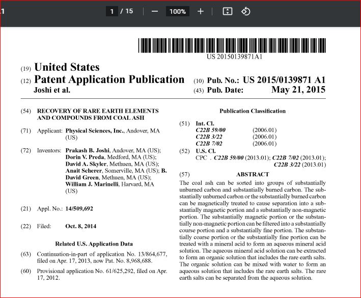
(19) United States (12) Patent Application Publication
(10) Pub. No.: US 2015/0139871 A1 Joshi et al. US 2015O139871A1
(43) Pub. Date: May 21, 2015
(54) (71) (72) (21) (22) (63) (60)
RECOVERY OF RARE EARTHELEMENTS AND COMPOUNDS FROM COAL ASH
Applicant: Physical Sciences, Inc., Andover, MA (US)
Inventors: Prakash B. Joshi, Andover, MA (US); Dorin V. Preda, Medford, MA (US); David A. Skyler, Methuen, MA (US); Anait Scherer, Somerville, MA (US); B. David Green, Methuen, MA (US); William J. Marinelli, Harvard, MA (US)
Appl. No.: 14/509,692
Filed: Oct. 8, 2014
Related U.S. Application Data Continuation-in-part of application No. 13/864,677, filed on Apr. 17, 2013, now Pat. No. 8,968,688. Provisional application No. 61/625,292, filed on Apr. 17, 2012. Publication Classification (51) Int. Cl. C22B59/00 (2006.01) C22B3/22 (2006.01) C22B 7/02 (2006.01) (52) U.S. Cl. CPC C22B59/00 (2013.01); C22B 7/02 (2013.01); C22B3/22 (2013.01)
(57) ABSTRACT The coal ash can be sorted into groups of Substantially unburned carbon and substantially burned carbon. The sub stantially unburned carbon or the substantially burned carbon can be magnetically treated to cause separation into a Sub stantially magnetic portion and a Substantially non-magnetic portion. The Substantially magnetic portion or the Substan tially non-magnetic portion can be filtered into a substantially course portion and a Substantially fine portion. The Substan tially coarse portion or the Substantially fine portion can be treated with a mineral acid to form an aqueous mineral acid Solution. The aqueous mineral acid solution can be extracted to form an organic solution that includes the rare earth salts. The organic Solution can be mixed with water to form an aqueous solution that includes the rare earth salts. The rare earth salts can be separated from the aqueous Solution.
Patent Application Publication May 21, 2015
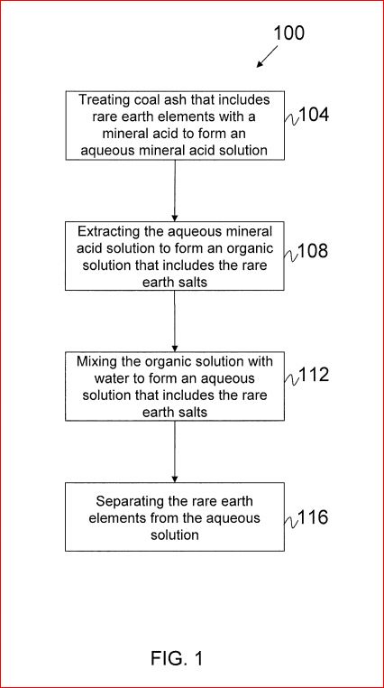
Sheet 1 of 7 US 2015/O139871 A1 100 Treating coal ash that includes rare earth elements with a 104 mineral acid to form an adueous mineral acid Solution Extracting the aqueous mineral acid Solution to form an organic 108 Solution that includes the rare earth Salts Mixing the organic solution with Water to form an adueous 112 Solution that includes the rare earth Salts Separating the rare earth elements from the adueous 116 Solution
FIG. 1 Patent Application Publication May 21, 2015
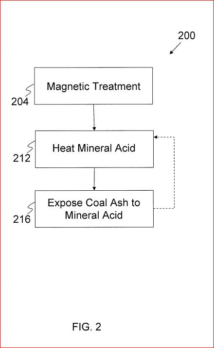
Sheet 2 of 7 US 2015/O139871 A1 2OO Magnetic Treatment Heat Mineral Acid Expose Coal Ash to Mineral Acid
FIG 2 Patent Application Publication May 21, 2015
HHHHH
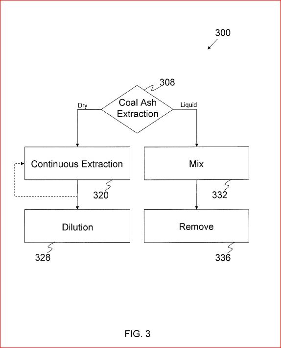
Sheet 3 of 7 US 2015/O139871 A1 3OO 3O8 Coal Ash Extraction Liquid --> g on 328 y 336
FIG 3 Patent Application Publication May 21, 2015
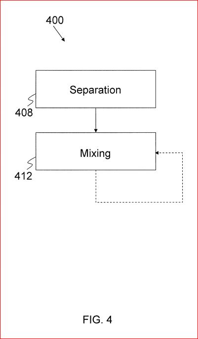
Sheet 4 of 7 US 2015/O139871 A1 4OO
FG. 4 Patent Application Publication May 21, 2015
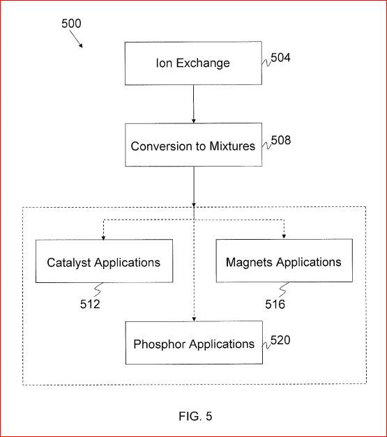
Sheet 5 of 7 US 2015/O139871 A1 s near lon Exchange 504 Conversion to Mixtures 508 Catalyst Applications : Magnets Applications s : 512 516 Phosphor Applications 520 Patent Application Publication May 21, 2015
FIG 5.
HHHHH
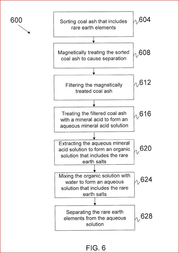
Sheet 6 of 7 US 2015/O139871 A1 600 Sorting Coal ash that includes 604 Y. rare earth elements Magnetically treating the sorted 608 Coal ash to cause separation Filtering the magnetically 612 treated coal ash Treating the filtered coal ash 616 With a mineral acid to form an aqueous mineral acid solution Extracting the aqueous mineral acid solution to form an organic 62O Solution that includes the rare rv earth Salts see Mixing the organic solution with water to form an adueous , 624 Solution that includes the rare earth Salts Separating the rare earth elements from the adueous Solution 628
FIG. 6
Patent Application Publication May 21, 2015
Sheet 7 of 7 US 2015/O139871 A1 700 Screen Coal Ash Perform Froth Floatation Gather Coal Ash 704 708 712
FIG. 7 US 2015/O 139871 A1 RECOVERY OF RARE EARTHELEMENTS AND COMPOUNDS FROM COAL ASH
https://link.springer.com/article/10.1007/s40789-016-0141-2
CROSS-REFERENCE TO RELATED APPLICATIONS
0001. This instant application is a continuation-in-part of U.S. patent application Ser. No. 13/864,677, filed on Apr. 17. 2013 and titled “Recovery of Rare Earth Elements and Com pounds from Coal Ash’, which claims the benefit of and priority to U.S. provisional patent application No. 61/625, 292, filed Apr. 17, 2012, the entire contents of which are incorporated by reference herein and owned by the assignee of the instant application.
FIELD OF THE INVENTION
0002 The invention relates generally to recovery of rare earth elements and/or compounds from coal ash.
BACKGROUND
0003. Rare earth elements can be fundamental to emerg ing green energy technologies in the United States
(e.g., per manent magnet motors for wind turbines and disk drives, hybrid car batteries, compact fluorescent lighting, and/or dis plays in all types of consumer/defense electronics),
as well as other usages such as industrial catalysts for refining heavier crude oil, automobile catalytic converters, and/or as alloying elements. Presently, rare earth elements can be obtained through mining.
0004 Coals from certain regions of the world can be par ticularly rich in rare earth elements, approaching a total con centration of about 1000 parts-per-million (ppm). The combustion of coal in power plants for energy generation concentrates non-volatile minerals in the ash by about ten times, to about 10,000 ppm, or on the order of approximately 1%. Coalash can be the product ofburning coal. Coalash can be comprised offly ash and bottomash. Fly ash can be ash that rises with flue gases. Bottomash can be ash that is found at the bottom of a furnace. Fly ash can be collected before the flue gases reach chimneys of power plants. 0005. A method to extract rare earth elements from coal is desired. The United States alone produces on the order of 100 million metric tons of fly ash annually. Accounting for pro cess yield and variability in rare earth element content, if rare earth elements are extracted from coal ash, a reasonable frac tion of currently available fly ash (e.g., about 10-15%) can be adequate to meet rare earth elements demand in the United States. SUMMARY OF THE INVENTION 0006 Advantages of the invention include recovering rare earth elements from coalash. Another advantage of the inven tion includes economical production of rare earth elements and/or compounds from alternative, non-mineral raw mate rials. Another advantage of the invention is the ability to build reliable production capabilities and/or supply chain for rare earth elements and/or byproducts. Another advantage of the invention is processing fly ash to recover rare earth materials, particularly heavier rare earths, more economically and energy-efficiently per kilogram of rare earth elements than from processing and extracting mineral resources. Another advantage includes the beneficiation of coal ash, which is an abundant waste material, for recovering economically useful and marketable industrial materials that include rare earth May 21, 2015 elements as a significant component. Another advantage includes energy efficient extraction of rare earth elements, which can save energy use by about 75% relative to conven tional mining per unit weight of rare earth elements produced. Yet another advantage is the accompanying carbon dioxide (CO) emission can be lower than mining by about 75%. Still another advantage includes production of environmentally beneficiated ash cake, which can be free of hazardous ele mentS. 0007. In one aspect, the invention involves a method of recovering rare earth elements from coal ash. The method involves sorting the coal ash into groups of Substantially unburned carbon and substantially burned carbon. The sub stantially unburned carbon or substantially burned carbon is magnetically treated to cause separation into a substantially magnetic portion and a substantially non-magnetic portion. The Substantially magnetic portion or the Substantially non magnetic portion is filtered into a Substantially course portion and a Substantially fine portion. The Substantially coarse por tion or the substantially fine portion is treated with a mineral acid to form an aqueous mineral acid solution that contains rare earth element salts. The aqueous mineral acid solution is extracted to form an organic Solution that includes the rare earth salts. The organic solution is mixed with water to form an aqueous Solution that includes the rare earth salts and the rare earth salts (or rare earth elements) are separated from the aqueous Solution. 0008. The aspect described above can include one or more of the following features. In some embodiments, sorting the coal ash can include Screening the coal ash to collect coal ash that is smaller than a first predefined size. Sorting the coal ash can also include performing froth floatation of the screened coal ash. The coal ash that does not float can be gathered. 0009. In various embodiments, screening the coal ash can be done using a scalping screen. The Substantially non-mag netic portion of the coal ash can be filtered by size. In some embodiments, cyclone separating removes coal ash that is smaller than a second predefined size. The substantially fine portion of the coal ash can be smaller than the second pre defined size. The substantially fine portion of the coal ash can be removed and used in a cement Substitute market. 0010. In some embodiments, the substantially coarse por tion of the coalash is treated with a mineral acid. The mineral acid can be nitric acid. 0011. In various embodiments, treating includes heating the mineral acid to approximately 90° C. The substantially coarse portion, the Substantially fine portion, or both can be exposed to the mineral acid for at least one hour. Exposing the coalash can include additional heating of a resulting Solution formed when exposing the coal ash to the mineral acid to generate a more concentrated mixture.
0012. In some embodiments, extracting the aqueous min eral acid solution also includes mixing the aqueous mineral acid solution with tributyl phosphate and kerosene. Extract ing the aqueous mineral acid solution can also include remov ing the organic Solution from the aqueous mineral acid solu tion such that the rare earth salts are substantially removed along with the organic solution. Extracting the aqueous min eral acid solution can further include performing a dry extrac tion, a liquid extraction, or any other combination. The dry extraction can be a Soxhlet extraction. The dry extraction can also include performing continuous extraction of rare earth salts with tributyl phosphate. US 2015/O 139871 A1
0013. In various embodiments, mixing the organic solu tion includes performing multiple cycles of mixing the organic solution with water until a concentration level of rare earth salts in the aqueous solution is below a predetermined threshold. In other embodiments, magnetically treating can include ion exchange separation. Ion exchange separation leading to rare earth element mixtures can be converted to mixtures of rare earth oxides and rare metals for various applications such as catalyst, magnets, and phosphor appli cations. 0014. Other aspects and advantages of the invention will become apparent from the following detailed description, taken in conjunction with the accompanying drawings, illus trating the principles of the invention by way of example only. BRIEF DESCRIPTION OF THE DRAWINGS 0015 The advantages of the invention described above, together with further advantages, may be better understood by referring to the following description taken in conjunction with the accompanying drawings. The drawings are not nec essarily to Scale, emphasis instead generally being placed upon illustrating the principles of the invention. 0016 FIG. 1 is a flow diagram of a method for extraction of rare earth elements from coal ash, according to an illustra tive embodiment of the invention. 0017 FIG. 2 is flow diagram of a method for treatment of coal ash, according to an illustrative embodiment of the invention. 0018 FIG. 3 is a flow diagram of a method for extraction of aqueous mineral acid solution, according to an illustrative embodiment of the invention. 0019 FIG. 4 is a flow diagram of a method for mixing organic solution, according to an illustrative embodiment of the invention. 0020 FIG. 5 is a flow diagram of a method for separation of rare earth elements, according to an illustrative embodi ment of the invention. 0021 FIG. 6 is a flow diagram of a method for extraction of rare earth elements from coal ash, according to an illustra tive embodiment of the invention. 0022 FIG. 7 is flow diagram of a method for sorting coal ash, according to an illustrative embodiment of the invention. DETAILED DESCRIPTION OF THE INVENTION 0023. A method of processing coal ash can be used to recover rare earth elements in order to, for example, meet critical rare earth element materials needs. The method can employ a closed looped schema e.g., certain materials, such as aqueous mineral acid, can be reused rather than discharged as waste. Since materials are reused, the closed-loop schema can have a lower environmental impact than, for example, mining for rare earth elements. 0024. The method can also allow exploitation of low grade sources of the rare earth elements. The method can utilize waste ash, e.g., ash that follows coal combustion, as a resource for rare earth elements. The method can allow ben eficiating the waste ash while simultaneously recovering rare earth elements. 0025. Rare earth elements principally include the lan thanide series of the periodic table, but the term can also incorporate Scandium and yttrium that are not true lan thanides. Exemplary rare earth elements, include: lanthanum (La), cerium (Ce), praseodymium (Pr), neodymium (Nd), May 21, 2015 promethium (Pm), Samarium (Sm), europium (Eu), gado linium (Gd), terbium (Tb), dysprosium (Dy), holmium (Ho), erbium (Er), thulium (Tm), ytterbium (Yb), lutetium (Lu), scandium (Sc) and yttrium (Y). Rare earth elements can include light rare earth elements, medium rare earth elements, and/or heavy rare earth elements. Exemplary light rare earth elements include Sc, La, Ce, Pr, Nd, and Pm. Exemplary medium rare earth elements include Sm, Eu, and Gd. Exem plary heavy rare earth elements include Tb, Dy, Ho, Er, Tm, Yb, Lu, and Y. 0026 Rare earthelements that are recovered from coal can have a number of applications. For example, some of these coals contain Y, a heavy rare earth element that can be used in compact fluorescent light bulbs. The coals can also contain Nd, a light rare earth element that can be used in permanent magnet motors in hybrid vehicles, wind turbines, and com puter disk drives. Other applications for rare earth elements can include, for example, use in aerospace components, high refractive index glass, flint, batteries, catalysts, polishes, lasers, X-ray machines and capacitors. (0027 FIG. 1 shows a flow diagram of a method 100 for extraction of rare earth elements from coal ash, according to an illustrative embodiment of the invention. The method 100 involves treating coal ash (e.g., mineral acid digestion) that includes rare earth elements (rare earth elements may be referred to as rare earth element salts) with a mineral acid to form an aqueous mineral acid solution (Step 104). The method also involves extracting the aqueous mineral acid solution to form an organic solution that includes the rare earth elements (Step 108). The method also involves mixing the organic solution with water to form an aqueous Solution that includes the rare earth elements (Step 112). The method also involves separating the rare earth elements from aqueous solution (Step 116). The method 100 can be a solvent extrac tion process. In some embodiments, the solvent extraction process uses a mineral acid that can be recovered and recycled to extract the rare earth elements from coal ash. 0028. In some embodiments, fly ash is used to extract the rare earth elements (as opposed to coal ash, which contains both fly ash and bottomash). Although fly ash and coal ashare not necessarily the same, any of the preceding and/or forego ing methods applied to fly ash can be applied to coal ash and Vice versa. In various embodiments, any of the preceding and/or foregoing methods applied to fly ash and/or coal ash can also be applied to bottom ash. 0029. In some embodiments, the mineral acid is nitric acid. In various embodiments, the rare earth element is a rare earth nitrate and the aqueous mineral acid solution is an aqueous nitric acid solution. In some embodiments, the min eral acid is selected based on a specific application for the rare earth elements. For example, nitric acid (7M) can be used in a PUREX (Plutonium Uranium Extraction) process (e.g., a process for the reprocessing of spent nuclear fuel to separate uranium and plutonium from the fission products and from one another) because the nitric acid can be used to dissolve used nuclear fuel. In some embodiments, the mineral acid is different from the hydrochloric and/or sulfuric acid mineral acids that are typically used for rare earth element extraction directly from mined minerals.
0030 FIG. 2 shows a flow diagram for a method 200 for the treatment of coal ash (e.g., Step 104 as described above in FIG. 1), according to an illustrative embodiment of the invention. The method 200 involves preprocessing the coal ash (Step 204). The preprocessing can be performed to concen US 2015/O 139871 A1 trate the coalash and can be eitheraphysical preprocessing or a chemical preprocessing. Concentrating the coal ash can involve exposing the coal ash to magnetic treatment (e.g., magnetic separation). Magnetic separation is a physical pre processing that can create a magnetic fraction that includes a Substantially magnetic fraction and a Substantially nonmag netic fraction. Other types of preprocessing of the coal ash can occur, including other physical preprocessing, Such as sieving (e.g., separating out a particle size range that does not contain the rare earth elements), and/or chemical preprocess ing, such as froth floatation (e.g., modifying the Surface prop erties of rare earth elements that containing certain com pounds such that the rare earth elements float to the top of a preprocess tank or sink to the bottom of the tank (reverse floatation)). 0031 Magnetic treatment can maximize efficiency of extracting the rare earth elements from coal ash by, for example, passing the coal ash through a magnetic separator before chemical processing. Certain types of coal ash can contain significant concentrations of magnetic iron oxides. For example, coal ash created from coals mined in Kentucky and/or countries such as Bulgaria can be particularly rich in magnetic iron oxides. By knowing which oxide is likely con centrated in a particular type of coal ash, magnetic separation can be used to concentrate the rare earth elements (e.g., pro duce a Substantially magnetic portion of coal ash). For example, if the rare earth elements found in fly ash are tied into magnetic spinal/glass structures, then the rare earth ele ments can be separated into the magnetic fraction. If the rare earth elements found in fly ash are not tied into magnetic spinal/glass structures, then the rare earth elements, which exist in their oxide forms in the coal ash, can separate into the non-magnetic fraction. Sampling and testing can be done to determine whether the rare earth elements are in the magnetic or non-magnetic fractions by, for example, using glow dis charge mass spectroscopy. Magnetic structures used to facili tate the magnetic separation can include magnetite (Fe-O). hematite (Fe2O), and/or other iron oxides Such as gamma Fe2O, or maghemite. 0032. The method 200 also involves heating a mineral acid (Step 212). The mineral acid can be a volume of 3 Normal (N) mineral acid. The mineral acid can be heated to approxi mately 90°C. In some embodiments, the mineral acid can be heated at any temperature between 60° C. and 95°C. The method 200 also involves exposing the coal ash to the mineral acid (Step 216). In some embodiments, the coal ash is exposed to the mineral acid for at least one hour. Exposing the coalash to the mineral acid can concentrate the amount of rare earth elements that are found in the coalash. In some embodi ments, after the coal ash is exposed to mineral acid, the coal ash is heated and exposed to the mineral acid again (e.g., repeat Steps 212 and 216, respectively). In various embodi ments, the number of times the coalash is heated and exposed to mineral acid can be 1, 2, 3, or any number of times. The type of rare earth element or coalash source can determine the number of times the coalash is heated and exposed to mineral acid. Additional heating (e.g., at a higher temperature and/or heating for a longer duration) of the mixture of the mineral acid and coal ash can generate a more concentrated mixture. A more concentrated mixture can contain more rare earth element then would occur if the additional heating was not applied. A resulting product of Step 216 can include an aque ous mineral acid solution, ash cake and gas. May 21, 2015 0033 FIG. 3 shows a flow diagram for a method 300 for the extraction of aqueous mineral acid solution, according to an illustrative embodiment of the invention (e.g., Step 108 as described above in FIG. 1). The method 300 involves extract ing treated coal ash (Step 308). Treated coal ash can be the product of procedures such as Step 104 or method 200. The treated coalash can include an aqueous mineral acid solution, ash cake and/or gas. The method 300 can involve mixing the aqueous mineral acid solution from the treated coal ash with tributyl phosphate and kerosene and removing the organic Solution from the aqueous mineral acid solution Such that rare earth salts are substantially removed with the organic solu tion. In some embodiments, Solutions such as ionic liquids, pivaloyltrifluoroacetone (HA), N-methyl-N-phenyl-1,10 phenanthroline-2-carboxamide (MePhPTA), 14,10,13 Tetrathia-7, 16-diazacyclooctadecane (ATCO) and/or ATCO binary extraction systems containing lauric acid can be used to mix with the aqueous mineral acid solution from the treated coal ash instead of tributyl phosphate and kerosene. 0034 Treated coal ash, such as the product of procedures such as Step 104 or method 200, can be subjected to an extraction method in Step 308. The extraction method can be a dry extraction, a liquid extraction or a combination of the dry extraction and the liquid extraction. The dry extraction can be done using Soxhlet extraction. The dry extraction can include the pre-concentration of the aqueous mineral acid Solution Such that a higher concentration of rare earth ele ments is present in the aqueous mineral acid solution. The pre-concentration can be performed in any manner known to those of skill in the art, including drying, which can enable, for example, continuous extraction of rare earth elements from dry rare earth salt concentrate and continuous recovery/ recycling of tributyl phosphate. In some embodiments, to minimize the amount of tributyl phosphate used in the extrac tion process, tributyl phosphate can be recovered after the extraction process and recycled in a future extraction process. This approach can have economic and environmental ben efits. Other steps to further concentrate the rare earth salt can be done to, for example, obtain higher yield efficiency. 0035. In some embodiments, if dry extraction is used, the method 300 also involves continuously extracting (Step 320). In Step 320, rare earth salts can be extracted from the aqueous mineral Solution of treated coal ash by capturing rare earth salts that are carried off in vapors formed by boiling tributyl phosphate mixed with the aqueous mineral Solution. Mixing the aqueous mineral Solution and tributyl phosphate can cre ate a solution containing an organic Solution and a mineral Solution. In some embodiments, the vapors pass through an extraction chamber. The extraction chamber can separate the rare earth salts from the vapors by allowing only the vapor to pass through to a condenser. The rare earth salts can be col lected in a ceramic or tissue paper thimble. The vapors that have passed through the extraction chamber can be converted back into the aqueous mineral Solution at the condenser. The aqueous mineral Solution collected at the condenser can be reintroduced and re-boiled.
0036 Step 320 can be repeated until a threshold for an amount or concentration of extracted rare earth salts is met. The threshold can be, for example, an amount (e.g., mass/ weight) of extracted rare earth salt or a concentration of rare earth salt in the collected aqueous mineral solution. Step 320 can also be performed for a pre-determined period of time. The period of time can be, for example, minutes, hours, days, etc. In some embodiments, the period of time can be a func US 2015/O 139871 A1 tion of a rare earth element concentration in the organic solution. Performing Step 320 multiple times can be desired to ensure that a desired amount of rare earth salts is extracted from the aqueous mineral Solution. If dry extraction is used, the method 300 can also involve diluting (Step 328). In some embodiments, the organic solution formed in Step 320 is diluted using kerosene. 0037. In various embodiments, if liquid extraction is used, the method 300 involves mixing (Step 332). The aqueous mineral acid solution of treated coal ash can be mixed with tributyl phosphate and kerosene. Mixing the aqueous mineral acid solution can create an aqueous mineral Solution that contains little to no rare earth elements and an organic solu tion that contains rare earth elements. If liquid extraction is used, the method 300 can also involve removing the organic solution (Step 336). In some embodiments, the organic solu tion is removed from the aqueous mineral acid. 0038. In various embodiments, the volume of tributyl phosphate and kerosene used in Step 332 is equal to the Volume of aqueous mineral acid solution. In various embodi ments, the Volume of tributyl phosphate and kerosene used in Step 332 is equal to a predetermined amount that is greater than the Volume of the aqueous mineral acid solution. The predetermined amount can be equal to any integer. For example, the predetermined amount can be equal to 9, ren dering the total volume used in Step 332 to be 10x the volume of aqueous mineral acid solution. In some embodiments, the volume of tributyl phosphate and the volume of kerosene are equal. In various embodiments, the total volume of tributyl phosphate and kerosene is equal to the predetermined amount greater than the Volume of aqueous mineral acid solution (including situations where the predetermined amount is 1: e.g., when the Volume of aqueous mineral acid solution is the same as the Volume of tributyl phosphate and kerosene). 0039. The initial concentrations of rare earth elements or salts in the coal ash mineral acid extract can affect an extrac tion efficiency of the rare earth element recovery process, particularly in the efficiency-limited extraction into tributyl phosphate/kerosene steps. Such as in Step 332. For example, a six to ten fold increase in the initial concentration can increase the extraction efficiency by over two-fold, depend ing on the specific rare earth elements found in the coal ash mineral acid extract. For example, the coal ash mineral acid extract can be concentrated to dryness and then re-dissolved in 3 Molar (M) mineral acid. In addition, the extraction into tributyl phosphate/kerosene steps, as described above, can be stirred continuously overnight, followed by a phase separa tion to improve the efficiency of extraction. Continuous stir ring can yield greater chances of removing all of or a signifi cant portion of the rare earth elements from the aqueous mineral Solution, such that the organic solution can contains all of or a significant portion of the rare earth elements that were originally in the aqueous mineral Solution. 0040. In some embodiments, an efficiency of the extrac tion into tributyl phosphate/kerosene steps can be increased by adding three times a volume of 80/20 tributyl phosphate/ kerosene (e.g., a mixture with a volume made up of 80% tributyl phosphate and 20% kerosene) to the aqueous mineral acid solution. For example, using an initial concentration of 2x of the aqueous mineral acid solution prior to extraction into a 50-50 wt % tributyl phosphate/kerosene mixture may not have an effect on the efficiency of the rare earth element extraction. However, increasing the concentration of the aqueous mineral acid solution after treating coal ash with May 21, 2015 mineral acid and before extraction into tributyl phosphate/ kerosene by evaporation with water can increase the concen tration by 6x to 10x over the baseline, depending on the specific rare earth elements found in the coal ash. For example, the concentration of aqueous mineral acid solution can be increased by adding three times the volume of tributyl phosphate/kerosene to the aqueous mineral acid solution (e.g., a 80-20 wt % mixture with a volume made up of 80% tributyl phosphate/kerosene and 20% aqueous mineral acid Solution). 0041. This process of concentrating the aqueous nitrate Solution by evaporation can significantly increase the extrac tion efficiency, particularly with respect to the heavy rare earth elements yttrium and dysprosium and also for the light rare earth elements such as Samarium. To improve the extrac tion efficiency further, the initial concentration can be further increased by water evaporation. Evaporation can be used all the way to dryness (e.g., all water has been evaporated). 0042. In addition, the extraction into tributyl phosphate/ kerosene steps, such as in Step 320, can be stirred continu ously overnight, followed by phase separation to improve the efficiency of extraction. 0043 A product of method 300 can include an organic Solution that includes rare earth salts and thorium salts, and an aqueous mineral acid solution with rare earth salts and tho rium salts removed (e.g., a second aqueous mineral acid solu tion different from the aqueous mineral acid found in the resulting product of Step 216). Other hazardous element salts can be removed as a result of method 300. In some embodi ments, the second aqueous mineral acid solution is distilled to recover mineral acid. The recovered mineral acid can be recycled and used to treat coal ash. Recycling mineral acid can contribute to making the recovery of rare earth elements more economical. The product of method 300 can result from either dry extraction or liquid extraction. 0044 FIG. 4 shows flow diagram for a method 400 for mixing organic solution, according to an illustrative embodi ment of the invention (e.g., Step 112 as described above in FIG. 1). The method 400 can involve separating (Step 408). A solution, such as the product of method 300, can be intro duced into the method 400. In Step 408, organic solution can be separated from other types of solution in the solution introduced into method 400 (e.g., an aqueous mineral acid solution). The organic solution that is separated in Step 408 can include rare earth salts. Step 408 can use any type of liquid separation method, including phase separation, evapo ration, and/or other similar methods. 0045 Phase separation can be conducted in a separator where organic solution separates to the top of the mixture and the aqueous solution separates from the organic Solution to the bottom of the mixture. The separated organic Solution can be re-extracted into water or re-extracted with dilute mineral acid to increase an extraction efficiency. The liquid used for re-extraction can be selected based on a determination of which liquid yields a better extraction efficiency. The organic Solution that includes thorium salts and aqueous solutions that includes rare earth salts only can be separated from one another after re-extraction.
0046. In some embodiments, the method 400 also involves mixing (Step 412). The organic Solution can be mixed with water to form an aqueous solution with rare earth salts and organic solution without rare earth salts. The aqueous solu tion can be removed resulting in a solution that is Substan tially organic solution. In some embodiments, a salt concen US 2015/O 139871 A1 tration check is performed on the Substantially organic Solution. If the Substantially organic solution contains a con centration level of rare earth salts above a predefined thresh old, Step 412 can be repeated. Step 412 can be repeated as many times as needed (e.g., until the salt concentration of the substantially organic solution is below the predefined thresh old). The predefined threshold can be a ratio of the salt con centration in the organic Solution versus the salt concentration in the aqueous solution. In some embodiments, the ratio can be 1:10 or 1:100. The ratio can also be dependant on the type ofrare earth salt that is being mixed. The threshold can also be dependant on whether it is monetarily worth extracting the rare earth slats at low concentrations. 0047 FIG. 5 shows a flow diagram for a method 500 for separation rare earth elements, according to an illustrative embodiment of the invention (e.g., Step 116 as described above in FIG. 1). In some embodiments, the method 500 involves ion exchange (Step 504). Rare earth salts can be separated from an aqueous solution using ion exchange. Ion exchange separation can only be used for the separation of rare earth elements from mixtures that contain Small amounts of rare earth elements. Ion exchange can use anion or cation exchange. 0048. The method 500 can also involve converting the rare earth salts into mixtures in (Step 508). These mixtures can include rare earth oxides or rare earth metals. The mixtures can include pre-selected nitrates Suitable for specific applica tions. Specific applications can include catalyst applications 512, magnets applications 516 and phosphor applications 520. In some embodiments, the process 500 separates the rare earth nitrites into individual rare-earth nitrates, such as Y. La, Ce, Nd, Dy, etc. 0049. In some embodiments, ion exchange also includes concentrating the aqueous solution to dryness and then dis solving dried solution in a solution containing 5% 7M min eral acid and 95% methanol. The dried salt solution can be loaded into an ion exchange column where it can be washed with a solution containing 5% 7M mineral acid and 95% methanol before undergoing ion exchange separation. In Vari ous embodiments, dried salt solutions enriched in heavy rare earth elements are eluted with a solution containing 55% 7M mineral acid and 55% methanol. Dried salt solutions enriched in light rare earth elements can be eluted with water. 0050. The separation of salt mixtures into various rare earth elements or rare earth salts forms instead of into specific rare earth oxides can have several advantages. Going directly from an aqueous solution with rare earth salts to rare earth oxides can require heating at high temperatures (e.g., about 700° C.) for a significant amount of time (e.g., about 1 hour). This high temperature process can require a significant amount of energy. These various rare earth salt forms can later be converted into separated forms of oxides but only if nec essary. If an application does not require a specific oxide, there can be an energy savings. An energy savings can amount to 1,200J/g. In addition, ion exchange can remove other metal nitrate contaminants from the nitrate mixtures. 0051 Process parameters (e.g., time, temperature, con centration) are nominal values and can be optimized by one of ordinary skill in the art to improve the yields for rare earth elements from coal ash, depending on, for example, the con centration of rare earth elements in the coal ash. 0.052 Ashcake, orash remainder, that can beformed in the process of recovering rare earth elements (e.g., the Solid resi due after mineral acid digestion) can be free of hazardous May 21, 2015 elements such as arsenic, cadmium, and thorium (e.g., haz ardous elements are removed from the ash cake in the process of recovering rare earth elements). Coal ash that does not go through the process of recovering rare earth elements can present an environmental hazard due to the presence of radio active thorium and toxic elements such as, for example, arsenic and cadmium. The ash cake formed in this process as a by product can be more environmentally friendly and there fore can be remediated or used in applications such as a building or road construction material. For example, the ash cake can be used as a Portland cement Substitute in concrete. In some embodiments, toxic elements, such as arsenic, are removed during mineral acid digestion steps (e.g., Step 600, as described below). In other embodiments, radioactive ele ments, such as thorium, are removed during re-extraction (e.g., Step 620, as described below). 0053 FIG. 6 shows a flow diagram of a method 600 for extraction of rare earth elements from coal ash, according to an illustrative embodiment of the invention. The method 600 involves additional steps to increase the concentration of rare earth elements as described by method 100 (e.g., the method 600 is the method 100 plus additional steps). Additional steps can be physical or chemical methods. These additional steps can increase the efficiency of the chemical extraction or enrichment of fly ash. Concentration of rare earth elements can be higher within aluminum, non-magnetic iron, or aluni mosilicate glass. In various embodiments, the increase in efficiency can be as much as 5 times or more. 0054 The method 600 involves sorting coal ash that includes rare earth elements (Step 604). In some embodi ments, Step 604 sorts coal ash into groups of Substantially unburned carbon and substantially burned carbon. Groups of substantially unburned carbon can be a mix of unburned and burned carbon in which there is more unburned carbon than burned carbon. Groups of substantially burned carbon can be a mix of unburned and burned carbon in which there is more burned carbon than unburned carbon. In some embodiments, groups of substantially unburned carbon contains 80% or more unburned carbon in a mixture of unburned and burned carbon. In various embodiments, groups of Substantially burned carbon contain 80% or more burned carbon in a mix ture of unburned and burned carbon. Additional details regarding Step 604 are described below by method 700.
0055. The method 600 also involves magnetically treating the sorted coal ash to cause separation (Step 608). Step 608 can separate the coalash into a Substantially magnetic portion and a Substantially non-magnetic portion. In some embodi ments, the proportion of the Substantially magnetic portion to substantially non-magnetic portion can be 80% or more. The proportion of the Substantially magnetic portion to Substan tially non-magnetic portion can depend on the type of mate rial that makes up the Substantially magnetic and the Substan tially non-magnetic portions. The proportion of the Substantially magnetic portion to Substantially non-magnetic portion of a type of ash can also depend on where the coal originated from, in which coal from certain regions of the world may yield more or less Substantially magnetic portions. For example, ash from one region can yield an approximate 10% substantially magnetic portion, whereas ash from another region can yield an approximate 35% substantially magnetic portion. The separation can be done using a magnet on the sorted coal ash to attract the Substantially magnetic portion. Other forms of magnetic treatment can include any US 2015/O 139871 A1 methodology using an electromagnetic field to draw out (or separate) Substantially magnetic material from non-Substan tially non-magnetic material. 0056. The method 600 also involves filtering the magneti cally treated coal ash (Step 612). Step 612 can filter the magnetically treated coal ash by size. For example, coal ash can be separated by ash that is greater than 75 microns, less than 25 microns and 25-75 microns. Filtering of Step 612 can cause coal ash to separate into a substantially course portion and a Substantially fine portion. Filtering of the magnetically treated coal ash can be done using a cyclone separator. 0057. In some embodiments, the cyclone separator removes coal ash that is Smaller than a predefined cyclone separator size. For example, the predefined cyclone separator size can be in the range of +500 mesh, +200 mesh, +60 mesh, +75 mesh, -60 mesh, -75 mesh, -200 mesh and -500 mesh. Fine coal ash can be smaller than the predefined cyclone separator size. Course coal ash can contain more crevices to hold rare earth elements. 0058. In some embodiments where the coal ash is sepa rated into a substantially fine portion, the substantially fine portion of coalash is removed and used in a cement Substitute market (e.g., the Substantially fine portion of coal ash can be sold to be used as an ingredient or component for cement). The substantially fine portion can be mixed with water and evaporated to create poZZolanic fine ash. PoZZloanic fine ash contains aluminosilicates and other compounds which can be substitutes for concrete. The substantially course portion of coal ash can be the portion of the coal ash that is treated with mineral acid (e.g., as in Step 616). Using coal ash as a cement Substitute can lower cost forcement manufacturers as well as global CO2 emissions, which is a by-product of the cement manufacturing process. 0059. The method 600 also involves treating filtered coal ash (e.g., mineral acid digestion) with a mineral acid to form an aqueous mineral acid solution (Step 616). The method also involves extracting the aqueous mineral acid solution to form an organic solution that includes the rare earth elements (Step 620). The method also involves mixing the organic solution with water to form an aqueous solution that includes the rare earth elements (Step 624). The method also involves separat ing the rare earth elements from aqueous solution (Step 628). The method 600 can be a solvent extraction process. In some embodiments, the Solvent extraction process uses a mineral acid that can be recovered and recycled to extract the rare earth elements from coal ash. 0060. In some embodiments, Step 616 is the same as Step 104 as described above in FIG. 1. Namely, Step 616 can involve treating coal ash (e.g., mineral acid digestion) that includes rare earth elements with a mineral acid to form an aqueous mineral acid solution. Step 620 can be the same as Step 108 as described above in FIG.1. Namely, Step 620 can involve extracting the aqueous mineral acid solution to form an organic Solution that includes the rare earth elements. Step 624 can be the same as Step 112 as described above in FIG.1. Namely, Step 624 can involve mixing the organic Solution with water to form an aqueous solution that includes the rare earth elements. Step 628 can be the same as Step 116 as described above in FIG. 1. Namely, Step 628 can involve separating the rare earth elements from aqueous solution. 0061 FIG. 7 shows a flow diagram for a method 700 of sorting of coal ash (e.g., Step 604 as described above in FIG. 6), according to an illustrative embodiment of the invention. The method 700 involves screening the coal ash (Step 704). May 21, 2015 Screening can be performed to collect coal ash of a certain size. In some embodiments, screening is done to collect coal ash that is Smaller than a predefined screening size. For example, the predefined screening size can be in the range of -200 to +500 mesh. Screening can be performed utilizing a Scalping screen. A scalping screen can have a +60 mesh (e.g., greater than 250 um). The scalping screen can also have a size of 500 mesh, +200 mesh, +75 mesh, -60 mesh, -75 mesh, -200 mesh and -500 mesh. As apparent to one of ordinary skill in the art, other forms of sorting (e.g., using a vibratory conveyor) can also be performed to collect coal ash of a certain size. 0062. The method 700 also involves preforming froth floatation (Step 708). Froth flotation can be done on the screened coal ash to separate the Substantially burned carbon and the substantially unburned carbon. The unburned carbon can be used in the activated carbon market. The method 700 also involves gathering the coal ash (Step 712). Step 712 can involve gathering the coal ash that does not float (e.g., the tailings). 0063. In some embodiments, the tailings from froth flota tion are the Substantially burned carbon, which are then mag netically treated. Magnetically treating the tailings can be done wet or dry. The Substantially magnetic portion can be used as a magnetic Substitute in the heavy media coal sepa ration market.
0064 One skilled in the art will realize the invention may be embodied in other specific forms without departing from the spirit or essential characteristics thereof. The foregoing embodiments are therefore to be considered in all respects illustrative rather than limiting of the invention described herein. Scope of the invention is thus indicated by the appended claims, rather than by the foregoing description, and all changes that come within the meaning and range of equivalency of the claims are therefore intended to be embraced therein.
What is claimed:
1. A method of recovering rare earth elements from coal ash, the method comprising:
A) sorting the coal ash into groups of (a) substantially unburned carbon and (b) substantially burned carbon;
B) magnetically treating at least one of the Substantially unburned carbon or the substantially burned carbon to cause separation into a substantially magnetic portion and a substantially non-magnetic portion;
C) filtering ~ at least one of the Substantially magnetic portion or the Substantially non-magnetic portion into a 1) substantially course portion and a 2) Substantially fine portion;
D) treating at least one of the Substantially coarse portion or the substantially fine portion with a mineral acid to form an aqueous mineral acid solution; extracting the aqueous mineral acid solution to form an organic solution that includes the rare earth salts;
E) mixing the organic solution with water to form an aqueous Solution that includes the rare earth salts;
and F) separating the rare earth salts from the aqueous solution.
2. The method of claim 1, wherein "sorting the coal ash further" comprises:
A) screening the coal ash - to collect coalash that is Smaller than a first predefined size; [ "screening the coal ash" ]
B) performing froth floatation of the screened coal ash; [ "froth floatation" ]
and C) gathering coal ash that does not float. [ gathering "coal ash" that does "not float" ]
3. The method of claim 2, wherein screening the coal ash further comprises utilizing a "scalping screen" . US 2015/O 139871 A1
( VIDEO : https://anacondaequipment.com/what-is-a-scalping-screen-anacondas-opinion-on-what-to-expect-from-a-scalping-screen/ : https://patentimages.storage.googleapis.com/9d/17/ee/f645e1cbe0571d/US20150139871A1.pdf )
4. The method of claim 1, wherein the substantially non magnetic portion of the coal ash is filtered by size.
[ "non magnetic" "coal ash" : DETERMINED BY HOLDING MAGNET NEAR SAMPLE (FIGURE 2) ] : https://www.osti.gov/servlets/purl/1431313
"... Enrichment of Rare Earth Elements from Coal and Coal By-Products by Physical Separations Ronghong Lin a,* , Bret Howard a , Elliot Roth a , Tracy Bank a,b , Evan Granite a and Yee Soong
a a U.S. Department of Energy, National Energy Technology Laboratory, 626 Cochrans Mill Road, P.O. Box 10940, Pittsburgh, PA 15236, United States. b AECOM, Pittsburgh, PA 15236, USA.
* Corresponding author: 1-412-386-5064; ronghong.lin@netl.doe.gov ..."
5. The method of claim 1, wherein filtering the exposed coal ash comprises cyclone separating the expose coal ash.
[ "cyclone" separat" "coal" "ash" : VIDEO ]
6. The method of claim 5, wherein cyclone separating removes coal ash that is Smaller than a second predefined size.
7. The method of claim 6, wherein the substantially fine portion of the coal ash is smaller than the second predefined S17C.
[ S17C > carbon steel pRTICLE SIZE : http://steeljis.com/jis_steel_datasheet.php?name_id=231 >
8. The method of claim 7, wherein the substantially fine portion of the coal ash is removed and used in a cement substitute market.
"substantially fine" portion of the "coal ash": HHHHHHH "cement substitute market" https://www.constrofacilitator.com/alternative-cement-substitutes-materials/
9. The method of claim 1, wherein the substantially coarse portion of the coal ash is treated with a mineral acid.
10. The method of claim 1, wherein the mineral acid is nitric acid.
11. The method of claim 1, wherein treating further com prises: heating the mineral acid to approximately 90° C.; and exposing the Substantially coarse portion, the Substantially fine portion, or both to the mineral acid for at least one hour.
12. The method of claim 11, wherein exposing the coalash further comprises additional heating of a resulting Solution formed when exposing the coal ash to the mineral acid to generate a more concentrated mixture.
13. The method of claim 1, wherein the extracting the aqueous mineral acid solution further comprises: May 21, 2015 mixing the aqueous mineral acid solution with tributyl phosphate and kerosene; and removing the organic Solution from the aqueous mineral acid solution Such that the rare earth salts are substan tially removed along with the organic solution.
14. The method of claim 1, wherein extracting the aqueous mineral acid solution further comprises performing a dry extraction, a liquid extraction, or any combination thereof.
15. The method of claim 14, wherein the dry extraction is a Soxhlet extraction. 16. The method of claim 15, wherein the dry extraction comprises performing continuous extraction of rare earth salts with tributyl phosphate.
17. The method of claim 1, wherein mixing the organic Solution comprises performing multiple cycles of mixing the organic Solution with water until a concentration level of rare earth salts in the aqueous solution is below a predetermined threshold.
18. The method of claim 1, wherein magnetically treating further comprises ion exchange separation.
19. The method of claim 18, wherein ion exchange separation leads to rare earth element mixtures suitable to be converted to mixtures of rare earth oxides and rare metals for various applications such as catalyst, magnets, and phosphor applications.
What is claimed (ORIGINAL):
1. A method of recovering rare earth elements from coal ash, the method comprising: sorting the coal ash into groups of Substantially unburned carbon and substantially burned carbon; magnetically treating at least one of the Substantially unburned carbon or the substantially burned carbon to cause separation into a substantially magnetic portion and a substantially non-magnetic portion; filtering at least one of the Substantially magnetic portion or the Substantially non-magnetic portion into a substan tially course portion and a Substantially fine portion; treating at least one of the Substantially coarse portion or the substantially fine portion with a mineral acid to form an aqueous mineral acid solution; extracting the aqueous mineral acid solution to form an organic solution that includes the rare earth salts; mixing the organic solution with water to form an aqueous Solution that includes the rare earth salts; and separating the rare earth salts from the aqueous solution.
2. The method of claim 1, wherein sorting the coal ash further comprises: screening the coalash to collect coalash that is Smaller than a first predefined size; performing froth floatation of the screened coal ash; and gathering coal ash that does not float.
3. The method of claim 2, wherein screening the coal ash further comprises utilizing a scalping screen. US 2015/O 139871 A1
4. The method of claim 1, wherein the substantially non magnetic portion of the coal ash is filtered by size. 5. The method of claim 1, wherein filtering the exposed coal ash comprises cyclone separating the expose coal ash. 6. The method of claim 5, wherein cyclone separating removes coalash that is Smaller than a second predefined size. 7. The method of claim 6, wherein the substantially fine portion of the coal ash is smaller than the second predefined S17C. 8. The method of claim 7, wherein the substantially fine portion of the coal ash is removed and used in a cement substitute market. 9. The method of claim 1, wherein the substantially coarse portion of the coal ash is treated with a mineral acid.
10. The method of claim 1, wherein the mineral acid is nitric acid.
11. The method of claim 1, wherein treating further com prises: heating the mineral acid to approximately 90° C.; and exposing the Substantially coarse portion, the Substantially fine portion, or both to the mineral acid for at least one hour.
12. The method of claim 11, wherein exposing the coalash further comprises additional heating of a resulting Solution formed when exposing the coal ash to the mineral acid to generate a more concentrated mixture.
13. The method of claim 1, wherein the extracting the aqueous mineral acid solution further comprises: May 21, 2015 mixing the aqueous mineral acid solution with tributyl phosphate and kerosene; and removing the organic Solution from the aqueous mineral acid solution Such that the rare earth salts are substan tially removed along with the organic solution.
14. The method of claim 1, wherein extracting the aqueous mineral acid solution further comprises performing a dry extraction, a liquid extraction, or any combination thereof.
15. The method of claim 14, wherein the dry extraction is a Soxhlet extraction. 16. The method of claim 15, wherein the dry extraction comprises performing continuous extraction of rare earth salts with tributyl phosphate.
17. The method of claim 1, wherein mixing the organic Solution comprises performing multiple cycles of mixing the organic Solution with water until a concentration level of rare earth salts in the aqueous solution is below a predetermined threshold.
18. The method of claim 1, wherein magnetically treating further comprises ion exchange separation.
19. The method of claim 18, wherein ion exchange separation leads to rare earth element mixtures suitable to be converted to mixtures of rare earth oxides and rare metals for various applications such as catalyst, magnets, and phosphor applications.
![]()
Address: N0.2555,Xiupu Road, Kangqiao
Industrial Area, Pudong, Shanghai


There are 17 rare earth elements, namely lanthanum, cerium, praseodymium, neodymium, promethium, samarium, europium, gadolinium, terbium, dysprosium, ymium, erbium, thulium, ytterbium, lutetium, scandium and yttrium. Rare earth elements have optical, electromagnetic and other physical characteristics. When rare earth elements are added into other materials, the quality and performance of products can be greatly improved, and the effect of "the Midas touch turns to gold" is known as the "vitamin" of modern industry. A common metaphor is that if oil is the blood of industry, rare earths are its vitamins. Rare earth minerals can be widely used in atomic energy, glass, petroleum, textile, boot leather, dyeing, petrochemical, optics, laser, hydrogen storage, display panel, magnetic materials and other industries. Nowadays the global demand for rare earth resources is huge for military, science, technology and people's livelihood.
The mineral composition of rare earth ores is complex and contains many minerals and gangue minerals, so it is not easy to separate rare earth ores. The appropriate beneficiation process can be selected based on the different physical and chemical properties of their minerals and associated gangue. Prominer also has a close relation with state-owned laboratories and industrial companies that have rich experience in rare earth beneficiation and concentration so we can provide professional services on rare earth beneficiation technology studies and concentration plant EPC services. The common rare earth beneficiation technology is as below
Gravity separation of rare earth minerals is carried out by using the density difference between rare earth minerals and gangue minerals. For example, coastal placer mineral containing rare earth often adopt gravity separation and rare earth vein ore always use gravity separation for pre-concentration.
The flotation of rare earth ores is one of the main methods for the separation of rare earth ores. It uses the difference of physical and chemical properties between the surface of rare earth minerals and associated minerals to separate them from associated gangue and other minerals to obtain effective rare earth concentrates. For example, in Baotou Bayan Obo ore, because the density and magnetism of fluorocarbon holmium ore and monazite are basically the same, flotation process is adopted, or after gravity separation in seashore placer, rare earth concentrate is often obtained from heavy sand by flotation.

Rare earth mineral magnetic separation aims at some rare earth minerals with weak magnetism or rare earth minerals accompanied with magnetite. The magnetic separator with different magnetic field intensity is used to separate rare earth minerals according to the different specific magnetization coefficients of rare earth minerals with associated gangue and other minerals. For example, weak magnetic separation is used to separate ilmenite from monazite in seashore placer, or high magnetic separation is used to separate monazite from zircon, quartz and other minerals. In flotation of rare earth ores, in order to simplify flotation process and save flotation reagents, high intensity magnetic separation technology is sometimes used to pre-enrich rare earth ores.


Rare earth ore electroseparation is mainly due to the fact that rare earth ore belongs to non-good conductor. Therefore, it can be separated from good conductive minerals by using its different conductivity from associated minerals. Generally, electrostatic separation is mostly used in the heavy sand concentrating operation after gravity separation of seashore placer.
Chemical beneficiation of rare earth ores is mostly used in rare earth deposits which are adhering to kaolin or clay in ionic form. The chemical beneficiation method of leaching first and then precipitating is adopted because of the solubility of rare earth ions in sodium chloride or ammonium sulfate solution. Or for soluble acid or fluorocarbonate rare earth ores which are prone to phase change at high temperature, flotation can be carried out first, enrichment can be carried out, and then purification by chemical mineral processing.


High Intensity Magnetic Separator

High Intensity Magnetic Separator
"... Baker reunites with "Dawn Burton", a fellow former federal prosecutor who served as deputy chief of staff to Comey at the FBI. Burton left the FBI in August 2019 -- and joined Twitter the next month as director of strategy and operations and counsel organization ..." SOURCE: https://news.bloomberglaw.com/esg/twitter-hires-former-fbi-general-counsel-amid-fight-with-trump
 < AND, Why did Susan & Hans - move to ZIP 45405 ?
Coal-ASH-2-REE-Certificate-of-CORRECTION.JPG
Dear Sirs & Madams - AKA "patent holders" [ also Battelle Research, King Ave. - Columbus, OHIO ( we hope you are listening!) ],
I am sorry to inform you - your "patent * " fails on two counts [that] are immediately evident (to me) an:
(a) "Environmental Scientist" [BS, UWGB, 1982] AND (b) the biological mother of one Dawn Marie Danielson (nee Burton) - born in the AM of August 22, 197?
- and now (c) - THE "attorney" for TWITTER - in Washington, D.C. [ see https://www.fbi.gov/history/directors/james-b-comey ]
(1.) The "illustrative embodiment" of the invention YOU SHOW is NOT an "illustrative embodiment" of anything - see "baseball cap" example;
In fact, my husband - of 39+ years - is a "digital science illustrator". What you "present" is called a "block diagram" - (!);
AND (2.) You did use US taxpayer funds - to perform the experiments & research critical to your discovery - related to "US Critical Materials".
* UNITED STATES PATENT NO.: US 8,968,688 B2 Joshi et al. date: Mar. 3, 2015 :: ( https://patentimages.storage.googleapis.com/b1/76/40/96ade5301b206b/US8968688.pdf )
Assignee: Physical Sciences, Inc., Andover, MA : http://www.psicorp.com/ : http://www.psicorp.com/contact-us > William J. Marinelli marinelli@psicorp.com; Intellectual Property Manager : E. Jennings Taylor : jenningstaylor@faradaytechnology.com [ https://sbir.nasa.gov/content/faraday-technology-inc-2 ]
"Coal Ash" "RARE EARTH" ELEMENTS
https://www.sierraclub.org/sierra/2021-2-march-april/feature/can-harvesting-rare-earth-elements-solve-coal-ash-crisis
On gathering Rare Earth Elements - by a selected US EPA agent - and "shredded by Susan [ with hyperlinks, comments, etc.] [ original PDF download > here ]
https://hansandcassady.org/RARE-Earth-Elements-01.html :: https://www.sciencedirect.com/science/article/pii/S1674987119300258
https://pubs.er.usgs.gov/publication/fs20193048 >>
 < SIZE
https://doi.org/10.3133/fs20193048 ( https://pubs.usgs.gov/fs/2019/3048/fs20193048.pdf )
"... To determine REE contents of fly ash components, we [USGS] used an instrument called an ion microprobe [ https://en.wikipedia.org/wiki/Sensitive_high-resolution_ion_microprobe ] that produces a primary beam of charged particles (ions) that is directed onto the sample.
The Stanford-USGS Sensitive High-Resolution Ion Microprobe with Reverse Geometry (SHRIMP-RG; Bacon and others, 2012) was chosen - because it has the appropriate sensitivity (detection limits in the parts per million ) [ one thing in a million things] and spatial resolution (spot diameter of 15 micrometers) required to select individual fly ash particles for analysis. [ related ]
When the primary ion beam of negatively charged oxygen ions (O2 − ) is directed onto a sample [of fly ash] , it generates secondary ions of the REEs that are positively charged.
These "secondary ions" are detected by the SHRIMP-RG (above) and quantified by comparing the output to standard reference materials ( NIST ) having known REE contents. ..."
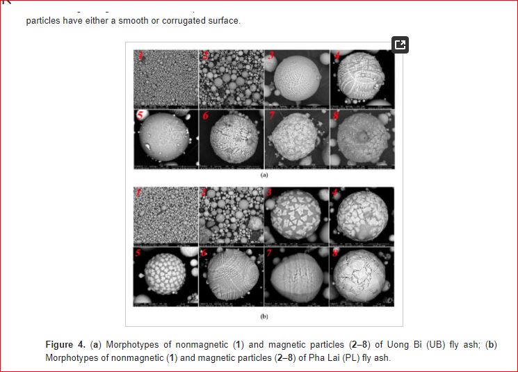
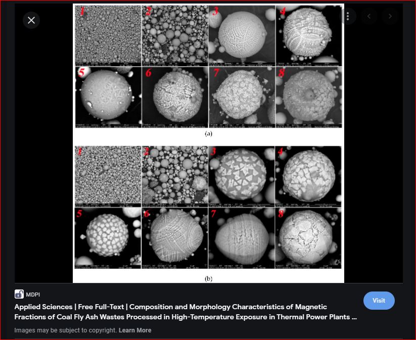
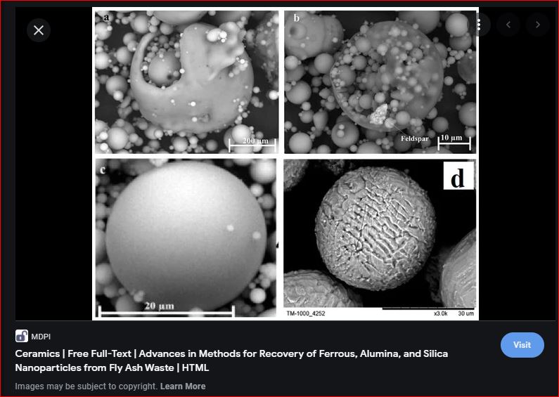
individual fly ash particles (VISUALS & the PHYSICS of shape )
| individual fly ash particles (VISUALS & the PHYSICS of shape ) - https://www.researchgate.net/figure/Individual-particle-types-in-Beijing-homes-a-individual-soot-aggregates-with_fig1_240279390 - https://cen.acs.org/articles/94/i7/New-Life-Coal-Ash.html - https://www.mdpi.com/2076-3417/9/9/1964/htm READ > https://www.sciencedirect.com/science/article/pii/S0360128517300795 TITLE: " Ash formation and deposition in coal and biomass fired combustion systems: Progress and challenges in the field of ash particle sticking and rebound behavior" - https://ars.els-cdn.com/content/image/1-s2.0-S0360128517300795-gr5_lrg.jpg - MicroscopicMorphologyandSizeDistributionofResidentialIndoorPM10inBeijingCity.pdf - https://ars.els-cdn.com/content/image/1-s2.0-S0360128517300795-gr6_lrg.jpg - https://ars.els-cdn.com/content/image/1-s2.0-S0360128517300795-gr9.jpg - https://ars.els-cdn.com/content/image/1-s2.0-S0360128517300795-gr13_lrg.jpg - https://ars.els-cdn.com/content/image/1-s2.0-S0360128517300795-gr21_lrg.jpg - https://ars.els-cdn.com/content/image/1-s2.0-S0360128517300795-gr22_lrg.jpg - https://ars.els-cdn.com/content/image/1-s2.0-S0360128517300795-gr39_lrg.jpg - https://ars.els-cdn.com/content/image/1-s2.0-S0360128517300795-gr45_lrg.jpg - https://ars.els-cdn.com/content/image/1-s2.0-S0360128517300795-gr67_lrg.jpg |
|||||||
| h | 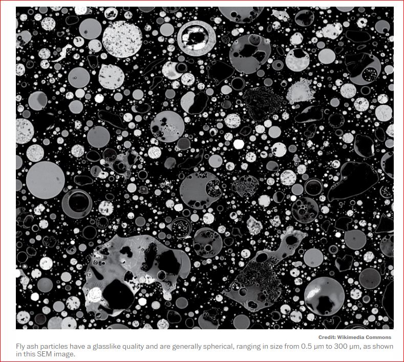 |
( better below ) |
|||||
 |
 |
||||||
 |
h |
SOURCE: https://en.wikipedia.org/wiki/Rare-earth_element#List
Z Symbol Name
21 Sc Scandium ( https://www.nist.gov/fusion-search?s=Scandium )
39 Y Yttrium
57 La Lanthanum
58 Ce Cerium
59 Pr Praseodymium
60 Nd Neodymium
61 Pm Promethium
62 Sm Samarium
63 Eu Europium
64 Gd Gadolinium
65 Tb Terbium
66 Dy Dysprosium
67 Ho Holmium
68 Er Erbium
69 Tm Thulium ( https://www.nist.gov/fusion-search?s=Thulium )
70 Yb Ytterbium ( https://www.nist.gov/fusion-search?s=Ytterbium )
71 Lu Lutetium ( https://www.nist.gov/fusion-search?s=Lutetium )
NIST > https://en.wikipedia.org/wiki/National_Institute_of_Standards_and_Technology : "... The National Institute of Standards and Technology (NIST) is a physical sciences laboratory and non-regulatory agency of the United States Department of Commerce. Its "mission" is to promote American innovation and industrial competitiveness.
NIST's activities are organized into "laboratory programs" that include nanoscale science and technology, engineering, information technology, neutron research, material measurement, and physical measurement. From 1901 to 1988, the agency was named the National Bureau of Standards. ..." [ https://www.nist.gov/ : https://www.nist.gov/publications ]
- "abandoned mines" > https://www.nist.gov/publications/search?k=abandoned+mines&d%5Bmin%5D=&d%5Bmax%5D=&t=&a=&s=All&n=
- https://www.nist.gov/publications/data-mining-electron-microscope-images-estimate-particle-size-distribution : Data Mining Electron Microscope Images to Estimate a Particle Size Distribution
- https://tsapps.nist.gov/publication/get_pdf.cfm?pub_id=820497
SOURCE: https://www.nist.gov/system/files/documents/2021/02/16/2021SRMCatalog_WEB.pdf
SOURCE: https://www.nist.gov/srm/about-nist-srms :
Industry, academia, and government use NIST SRMs to facilitate commerce and trade and to advance research and development. Presently NIST SRMs are currently available for use in areas such as industrial materials production and analysis, environmental analysis, health measurements and basic measurements in science and metrology. NIST SRMs are also one mechanism for supporting measurement traceability in the United States.
Each NIST Standard Reference Material® is supplied with a Certificate of Analysis and a Materials Safety Data Sheet, when applicable. In addition, NIST has published many articles and practice guides that describe the development, analysis and use of SRMs.
The SRM Program references a number of definitions in connection with the production, certification, and use of its SRMs and RMs. Certain definitions, adopted for SRM use, are derived from international guides and standards on reference materials and measurements while others have been developed by the SRM Program to describe those activities unique to NIST operations.
An NTRM (NIST Traceable Reference Material) is a commercially produced reference material with a well-defined traceability linkage to existing NIST standards. This traceability linkage is established via criteria and protocols defined by NIST. Commercial reference materials producers may affix the NTRM trademark to materials produced according to these criteria and protocols.
Links to the laboratories at NIST that produce SRMs:
?SOURCE: https://www-s.nist.gov/srmors/viewTable.cfm?tableid=39
Spectrometry, Single Element Standard Solutions These Standard Reference Materials (SRMs) are intended as the primary calibration standards for the quantitative determinations of a single element, typically using inductively coupled plasma optical emission spectrometry and/or inductively coupled plasma mass spectrometry. They can also be used in conjunction with any other analytical technique or procedure where standard solutions are required.
The SRM is a single-element solution of 50 mL with a nominal concentration of 10 mg/g and is provided as either a single high-density polyethylene bottle or in 5 x 10 mL borosilicate glass ampoules. Solutions may contain a nominal amount of acid, such as 10 % Nitric acid or 10 % Hydrochloric acid. SRM Description Unit of Issue 3101a Aluminum (Al) Standard Solution 5 x 10 mL 3102a Antimony (Sb) Standard Solution 50 mL 3103a Arsenic (As) Standard Solution 5 x 10 mL 3104a Barium (Ba) Standard Solution 50 mL 3105a Beryllium (Be) Standard Solution 5 x 10 mL 3106 Bismuth (Bi) Standard Solution 5 x 10 mL 3107 Boron (B) Standard Solution 50 mL 3108 Cadmium (Cd) Standard Solution 5 x 10 mL 3109a Calcium (Ca) Standard Solution 5 x 10 mL 3110 Cerium (Ce) Standard Solution 5 x 10 mL 3111a Cesium (Cs) Standard Solution 5 x 10 mL 3112a Chromium (Cr) Standard Solution 5 x 10 mL 3113 Cobalt (Co) Standard Solution 5 x 10 mL 3114 Copper (Cu) Standard Solution 50 mL 3115a Dysprosium (Dy) Standard Solution 5 x 10 mL 3116a Erbium (Er) Standard Solution 5 x 10 mL
( https://netl.doe.gov/sites/default/files/netl-file/Rare-Earth-Trace-Bulk-Elemental-Analysis-ICP-MS-Topical-Report-4-14-2016.pdf )
h Table 1. Certified and consensus values of rare earth elements in SBC-1, SGR-1b, and SRM 1632a. All concentrations in mg/kg. Values in italics are non-certified consensus or informational data. Element SBC-1 SGR-1b SRM 1632a Sc 20 4.6 ± 0.7 6.3 Y 36.5 13 9 La 52.5 20 ± 1.8 15 Ce 108.2 36 ± 4 30 Pr 12.6 3.15 Nd 49.2 16 ± 1.7 12 Sm 9.62 2.7 ± 0.3 2.4 Eu 1.98 0.56 ± 0.09 0.52 Gd 8.54 2 2.6 Tb 1.23 0.311 Dy 7.1 1.9 2.06 Ho 1.36 0.4 0.36 Er 3.79 1.1 0.91 Tm 0.56 0.17 0.39 Yb 3.64 0.94 1.08 Lu 0.54 0.17 Effects of sample preparation. F
Samples used in this study include the carbon-poor Brush Creek Shale from Pennsylvania ( SBC-1 ), an oil-rich Green River Shale from Wyoming ( SGR-1b ), and a NIST coal standard ( SRM 1632a ). Of these standard reference materials, only the SGR-1b [ Green River Shale from Wyoming ] has certified values for some of the REE, however published consensus values for the other standards are available for many of the rare earth elements.
- Additionally, values for many REE were also compared to a certified natural water standard ( T221 ) from the USGS Water Resources Division.
SERMIN1 and VIDAC18
( https://www.researchgate.net/publication/229527275_SERMIN1_and_VIDAC18_Two_proposed_reference_materials_for_rare_earth_element_determination_in_groundwater )
[ 15 micrometers = 0.000590551 inches ] > CHECK: 1 micrometer = 3.93701e-5 inches x 15 = 0.0005905515
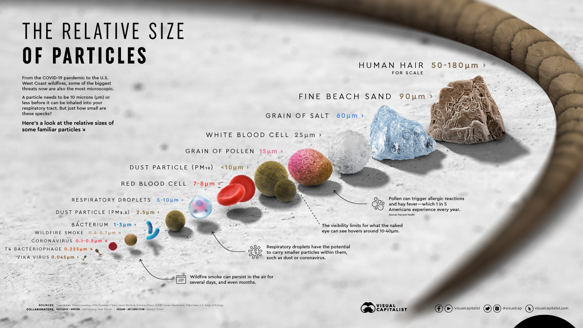
"OBJECTS" THAT ARE 1 micrometer IN SIZE > Micrometer 10-6 0.000001 One Millionth A single cell :: "SIZE" SARS-COV-2
coal ash ( https://www.epa.gov/coalash/coal-ash-basics )
Coal ash, also referred to as coal combustion residuals or CCRs, is produced primarily from the burning of coal in coal-fired power plants.
Coal ash includes a number of by-products produced from burning coal, including:
Other types of by-products are:
Fly ash can be classified according to the type of coal from which the ash was derived.
There are basically four types/ranks of coal:
anthracite,
bituminous,
sub-bituminous,
and lignite. The principal components of bituminous coal fly ash are:
silica,
alumina,
iron oxide,
and calcium,
with varying amounts of carbon.
Physical, chemical, and geotechnical properties of coal fly ash >
www.sciencedirect.com/science/article/pii/S2214509518303735#:~:text=Fly%20ash%20can%20be%20classified,with%20varying%20amounts%20of%20carbon.
SOURCE:
https://www.sciencedirect.com/science/article/pii/S2214509518303735#:~:text=Fly%20ash%20can%20be%20classified,with%20varying%20amounts%20of%20carbonFly ash Utilization Modes for EU, US, India and China.
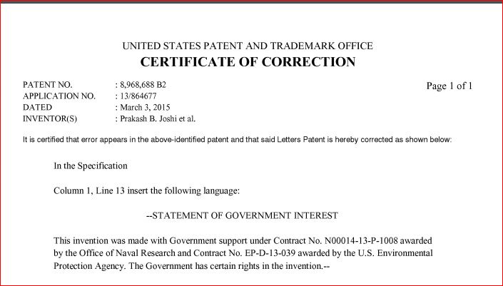
United States Patent 8,968,688 Joshi , et al. March 3, 2015 **Please see images for: ( Certificate of Correction ) **
TITLE: Recovery of rare earth elements and compounds from coal ash
Abstract: Rare earth elements are recovered from coal ash. The coal ash with rare earth elements can be treated with a mineral acid to form an aqueous mineral acid solution. The aqueous mineral acid solution can be extracted to form an organic solution that includes the rare earth salts. The organic solution can be mixed with water to form an aqueous solution that includes the rare earth salts. The rare earth elements are separated from the aqueous solution.
URL: https://patft.uspto.gov/netacgi/nph-Parser?Sect1=PTO2&Sect2=HITOFF&u=%2Fnetahtml%2FPTO%2Fsearch-adv.htm&r=24&f=G&l=50&d=PTXT&p=1&p=1&S1=((((PSI.ASNM.+AND+Andover.ASCI.)+OR+(Physical.ASNM.+AND+Andover.ASCI.))+OR+(((Moulton.INNM.+AND+((%22Schwartz+Electro-Optic%22.INNM.)+OR+%22Schwartz+Electro-Optics%22))+OR+(5029179+OR+5235610).PN.)+NOT+5740190.PN.))+OR+(Faraday.ASNM.+AND+(%22OH%22.ASST.)))&OS=+(an/PSI+and+ac/Andover)+or+(an/Physical+and+ac/Andover)+or+(in/Moulton+and+(in/%22Schwartz+Electro-Optic%22+or+%22Schwartz+Electro-Optics%22)+or+pn/(5029179+or+5235610)+ANDNOT+pn/5740190)+OR+(an/Faraday+and+as/OH)&RS=((((AN/PSI+AND+AC/Andover)+OR+(AN/Physical+AND+AC/Andover))+OR+(((IN/Moulton+AND+(IN/%22Schwartz+Electro-Optic%22+OR+%22Schwartz+Electro-Optics%22))+OR+PN/(5029179+OR+5235610))+ANDNOT+PN/5740190))+OR+(AN/Faraday+AND+AS/OH))
Inventors: Joshi; Prakash B. (Andover, MA) - http://www.psicorp.com/content/psi-annual-technical-achievement-awards-3 [photo]
, Preda; Dorin V. (Medford, MA),
Skyler; David A. (Methuen, MA), Tsinberg; Anait (Somerville, MA), Green; B. David (Methuen, MA), Marinelli; William J. (Harvard, MA) ...
![[US Patent & Trademark Office, Patent Full Text and Image Database]](https://patft.uspto.gov/netaicon/PTO/patfthdr.gif)
![[Home]](https://patft.uspto.gov/netaicon/PTO/home.gif) ![[Boolean Search]](https://patft.uspto.gov/netaicon/PTO/boolean.gif) ![[Manual Search]](https://patft.uspto.gov/netaicon/PTO/manual.gif) ![[Number Search]](https://patft.uspto.gov/netaicon/PTO/number.gif) ![[Help]](https://patft.uspto.gov/netaicon/PTO/help.gif) |
![[HIT_LIST]](https://patft.uspto.gov/netaicon/PTO/hitlist.gif) ![[NEXT_LIST]](https://patft.uspto.gov/netaicon/PTO/nextlist.gif) ![[PREV_DOC]](https://patft.uspto.gov/netaicon/PTO/prevdoc.gif) ![[NEXT_DOC]](https://patft.uspto.gov/netaicon/PTO/nextdoc.gif) ![[Bottom]](https://patft.uspto.gov/netaicon/PTO/bottom.gif) |
![[View Shopp
ing Cart]](https://patft.uspto.gov/netaicon/PTO/cart.gif) ![[Add to Shopping Cart]](https://patft.uspto.gov/netaicon/PTO/order.gif) |
![[Image]](https://patft.uspto.gov/netaicon/PTO/image.gif) |
| ( 24 of 123 ) |
| United States Patent | 8,968,688 |
| Joshi , et al. | March 3, 2015 |
| **Please see images for: ( Certificate of Correction ) ** |
Recovery of rare earth elements and compounds from coal ash
| Inventors: | Joshi; Prakash B. (Andover, MA), Preda; Dorin V. (Medford, MA), Skyler; David A. (Methuen, MA), Tsinberg; Anait (Somerville, MA), Green; B. David (Methuen, MA), Marinelli; William J. (Harvard, MA) | ||||||||||
|---|---|---|---|---|---|---|---|---|---|---|---|
| Applicant: |
|
||||||||||
| Assignee: | Physical Sciences, Inc. (Andover, MA) | ||||||||||
| Family ID: | 49477467 | ||||||||||
| Appl. No.: | 13/864,677 | ||||||||||
| Filed: | April 17, 2013 |
| Document Identifier | Publication Date | |
|---|---|---|
| US 20130287653 A1 | Oct 31, 2013 | |
| Application Number | Filing Date | Patent Number | Issue Date | ||
|---|---|---|---|---|---|
| 61625292 | Apr 17, 2012 | ||||
| Current U.S. Class: | 423/21.5 |
| Current CPC Class: | C22B 59/00 (20130101); C22B 7/007 (20130101); Y02P 10/234 (20151101); Y02P 10/20 (20151101) |
| Current International Class: | C22B 59/00 (20060101) |
| 4649031 | March 1987 | Matyas et al. |
| 2293134 | Feb 2007 | RU | |||
| 2293134 | Feb 2007 | RU | |||
Translation of RU2293134, Feb. 2007. cited by examiner . Joshi, P.B. and Skyler, D.A., "Recovery of Rare Earths from Coal Ash--Technology and Economics", Presentations to Dr. Victor H. Reis, Senior Advisor, Office of the Undersecretary of Energy for Science Department of Energy, Sep. 27, 2010, Dr. Nese Orbey, et al., University of Massachusetts, Lowell, Nov. 3, 2010 and Dec. 23, 2010. cited by applicant . Recovery of Critical Elements from Industrial Waste, Concept Paper submitted to the U.S. Department of Energy, Energy Efficiency and Renewable Energy Golden Field Office, DE-FOA-0000560, Innovative manufacturing Initiative, Sep. 21, 2011. cited by applicant . "A Low-cost Rare Earth Elements Recovery Technology", Physical Sciences Inc., Proposal #67152, Submitted to Nine Sigman, Jun. 17, 2011. cited by applicant . "A Low-cost Rare Earth Elements recovery Technology", Physsical Science Inc. Proposal #7361-073, Submitted to U.S. Environmental Protection Agency, May 3, 2011. cited by applicant . A Low-cost Rare Earth Elements Recovery Technology, A White Paper submitted in response to Broad Agency Announcement, BAA-DLASM-2011-01, National Defense Stockpile Research, Defense Logistics Agency (DLA), Strategic materials NDS research, Physical Sciences, Inc., WP12-09, Sep. 2, 2011. cited by applicant . Coal Ash: 130 Million Tons of Waste, CBS News, Apr. 15, 2010. cited by applicant . Seredin, V.V., "Rare Earth Element-Bearing Coals from the Russian Far East Deposits," Int. J. Coal Geology, vol. 30, 1996, pp. 101-129. cited by applicant . Hower, J.C., et al., "Lanthanide, yttrium, and zirconium anomalies in the Fire Clay coal bed, Eastern Kentucky,"International Journal of Coal Geology, vol. 39, 1999, p. 141-153. cited by applicant . Joshi, P.B., "Recovery of Rare Earth Elements from Coal Ash--Rationale and Approaches", Presentation to Mark Johnson, ARPE-E and Diana Bauer and Jennifer Li, DoE, Washington, DC, Feb. 9, 2011, Physical Sciences Inc. VG 11-027. cited by applicant . 2008 Coal Combustion Product (CCP) Production & Use Survey Report, AM Coal Ash Assn., 2008. cited by applicant . USGS Coal Quality Database, National Coal Resources Data System, 2004, http://energy.er.usgs.gov/coalqual.htm, Printed Aug. 29, 2014. cited by applicant . Kentucky Coal Quality Database, univ. of Kentucky Center for Applied Energy Research, 2010, http://kgs.uky.edu/kgsweb/DataSearching/coalsearch.asp, Printed Aug. 29, 2014. cited by applicant. |
US20130287653A1 > https://patents.google.com/patent/US20130287653A1/en
Primary Examiner: Bos; Steven
Attorney, Agent or Firm: Proskauer Rose LLP A [ https://en.wikipedia.org/wiki/Proskauer_Rose ] >> https://www.proskauer.com/alert/epa-proposes-to-revise-underground-storage-tank-regulations
https://images.law.com/contrib/content/uploads/documents/403/31848/NCAAHagensBerman.pdf
CROSS-REFERENCE TO RELATED APPLICATIONS
This application claims the benefit of and priority to U.S. provisional patent application no. 61/625,292, filed Apr. 17, 2012, the entire contents of which are incorporated by reference herein and owned by the assignee of the instant application.
NOT PUBLISHED > https://www.kaufholdpatentgroup.com/patent-search-are-provisional-patents-published/#:~:text=Once%20published%2C%20you%20can%20view,a%20period%20of%2012%2Dmonths.
( https://www.uspto.gov/patents/basics/types-patent-applications/provisional-application-patent )
"... A provisional patent application allows you to file without a formal patent claim, oath or declaration, or any information disclosure (prior art) statement.
Since June 8, 1995, the United States Patent and Trademark Office (USPTO) has offered inventors the option of filing a provisional application for patent which was designed to provide a lower-cost first patent filing in the United States and to give U.S. applicants parity with foreign applicants under the GATT Uruguay Round Agreements.
A provisional application for patent (provisional application) is a U.S. national application filed in the USPTO under 35 U.S.C. §111(b). A provisional application is not required to have a formal patent claim or an oath or declaration. Provisional applications also should not include any information disclosure (prior art) statement since provisional applications are not examined. A provisional application provides the means to establish an early effective filing date in a later filed nonprovisional patent application filed under 35 U.S.C. §111(a). It also allows the term "Patent Pending" to be applied in connection with the description of the invention.
A provisional application for patent has a pendency lasting 12 months from the date the provisional application is filed. The 12-month pendency period cannot be extended. Therefore, an applicant who files a provisional application must file a corresponding nonprovisional application for patent (nonprovisional application) during the 12-month pendency period of the provisional application in order to benefit from the earlier filing of the provisional application. However, a nonprovisional application that was filed more than 12 months after the filing date of the provisional application, but within 14 months after the filing date of the provisional application, may have the benefit of the provisional application restored by filing a grantable petition (including a statement that the delay in filing the nonprovisional application was unintentional and the required petition fee) to restore the benefit under 37 CFR 1.78.
..."
What is claimed:
1. A method of recovering rare earth elements in a form of rare earth salts from coal ash, the method comprising: preprocessing coal ash to concentrate the coal ash; treating the concentrated coal ash that includes rare earth elements with a mineral acid to form an aqueous mineral acid solution that includes rare earth salts and an ash cake, wherein the ash cake is formed free of hazardous elements; evaporating the aqueous mineral acid solution to a concentrate; extracting the concentrated aqueous mineral acid solution to form an organic solution that includes the rare earth salts; mixing the organic solution with water to form a second aqueous solution that includes the rare earth salts; and separating the rare earth salts from the second aqueous solution.
2. The method of claim 1, wherein the mineral acid is nitric acid.
3. The method of claim 1, wherein treating the concentrated coal ash further comprises: heating the mineral acid to approximately 90.degree. C.; and exposing the concentrated coal ash to the mineral acid for at least one hour.
4. The method of claim 3, wherein exposing the concentrated coal ash further comprises additional heating of a resulting solution formed when exposing the concentrated coal ash to the mineral acid to generate a more concentrated mixture.
5. The method of claim 1, wherein the extracting the concentrated aqueous mineral acid solution further comprises: mixing the concentrated aqueous mineral acid solution with tributyl phosphate and kerosene; and removing the organic solution from the concentrated aqueous mineral acid solution such that the rare earth salts are substantially removed along with the organic solution.
6. The method of claim 1, wherein extracting the concentrated aqueous mineral acid solution further comprises performing a dry extraction, a liquid extraction, or any combination thereof.
7. The method of claim 6, wherein the dry extraction is a Soxhlet extraction.
8. The method of claim 6, wherein the dry extraction comprises performing continuous extraction of rare earth salts with tributyl phosphate.
9. The method of claim 8, wherein the dry extraction further comprises diluting the organic solution with kerosene.
10. The method of claim 6, wherein the liquid extraction comprises: mixing a volume of tributyl phosphate and kerosene equal to a volume of the concentrated aqueous mineral acid solution; and removing the organic solution from the concentrated aqueous mineral acid solution.
11. The method of claim 6, wherein the liquid extraction comprises: mixing a volume of tributyl phosphate and kerosene that is a predetermined amount greater than a volume of the concentrated aqueous mineral acid solution; and removing the organic solution from the concentrated aqueous mineral acid solution.
12. The method of claim 11, wherein the predetermined amount is 9 times the volume of the concentrated aqueous mineral acid solution.
13. The method of claim 1, wherein mixing the organic solution comprises performing multiple cycles of mixing the organic solution with water until a concentration level of rare earth salts in the concentrated aqueous solution is below a predetermined threshold.
14. The method of claim 1, further comprising exposing the concentrated coal ash to a magnetic treatment such that the concentrated coal ash separates into a substantially magnetic portion and a substantially non-magnetic portion of the concentrated coal ash.
15. The method of claim 1, wherein separating the rare earth salts comprises an ion exchange separation using either anion or cation exchange.
16. The method of claim 15, wherein the ion exchange separation leads to rare earth salt mixtures suitable to be converted to mixtures of rare earth oxides and rare metals, the mixtures of rare earth oxides and rare metals are used to make catalysts, magnets, and phosphors.
17. The method of claim 1, wherein extracting the concentrated aqueous mineral acid solution forms a second aqueous mineral acid solution.
18. The method of claim 17, further comprising distilling the second aqueous mineral acid solution to recover mineral acid.
19. The method of claim 1, further comprising: recovering the ash cake from the concentrated aqueous mineral acid solution; and using the ash cake in building or road construction materials.
FIELD OF THE INVENTION
The invention relates generally to recovery of rare earth elements and/or compounds from coal ash.
BACKGROUND
Rare earth elements can be fundamental to emerging green energy technologies in the United States (e.g., permanent magnet motors for wind turbines and disk drives, hybrid car batteries, compact fluorescent lighting, and/or displays in all types of consumer/defense electronics), as well as other usages such as industrial catalysts for refining heavier crude oil, automobile catalytic converters, and/or as alloying elements. Presently, rare earth elements can be obtained through mining.
Coals from certain regions of the world can be particularly rich in rare earth elements, approaching a total concentration of about 1000 parts-per-million ("ppm"). The combustion of coal in power plants for energy generation concentrates non-volatile minerals in the ash by about ten times, to about 10,000 ppm, or on the order of approximately 1%. Coal ash can be the product of burning coal. Coal ash can be comprised of fly ash and bottom ash. Fly ash can be ash that rises with flue gases. Bottom ash can be ash that is found at the bottom of a furnace. Fly ash can be collected before the flue gases reach chimneys of power plants.
A method to extract rare earth elements from coal is desired. The United States alone produces on the order of 100 million metric tons of fly ash annually. Accounting for process yield and variability in rare earth element content, if rare earth elements are extracted from coal ash, a reasonable fraction of currently available fly ash (e.g., about 10-15%) can be adequate to meet rare earth elements demand in the United States.
SUMMARY OF THE INVENTION
Advantages of the invention include recovering rare earth elements from coal ash. Another advantage of the invention includes economical production of rare earth elements and/or compounds from alternative, non-mineral raw materials. Another advantage of the invention is the ability to build reliable production capabilities and/or supply chain for rare earth elements and/or byproducts. Another advantage of the invention is processing fly ash to recover rare earth materials, particularly heavier rare earths, more economically and energy-efficiently per kilogram of rare earth elements than from processing and extracting mineral resources. Another advantage includes the beneficiation of coal ash, which is an abundant waste material, for recovering economically useful and marketable industrial materials that include rare earth elements as a significant component. Another advantage includes energy efficient extraction of rare earth elements, which can save energy use by about 75% relative to conventional mining per unit weight of rare earth elements produced. Yet another advantage is the accompanying carbon dioxide (CO.sub.2) emission can be lower than mining by about 75%. Still another advantage includes production of environmentally beneficiated ash cake, which can be free of hazardous elements.
In one aspect, the invention involves a method of recovering rare earth elements from coal ash. The method involves treating coal ash that contains rare earth elements with a mineral acid to form an aqueous mineral acid solution. The aqueous mineral acid solution is extracted to form an organic solution that includes the rare earth salts. The organic solution is mixed with water to form an aqueous solution that includes the rare earth salts. The rare earth elements are recovered by separating the rare earth elements from the aqueous solution.
The aspect described above can include one or more of the following features. In some embodiments, the mineral acid is nitric acid. In various embodiments, treating coal ash can include heating the mineral acid to approximately 90.degree. C. and exposing the coal ash to the mineral acid for at least one hour. Exposing the coal ash can also include additional heating of a resulting solution formed when exposing the coal ash to the mineral acid in order to generate a more concentrated mixture.
In various embodiments, extracting the aqueous mineral acid solution includes mixing aqueous mineral acid solution with tributyl phosphate and kerosene and removing the organic solution from the aqueous mineral acid solution such that the rare earth salts are substantially removed along with the organic solution
In some embodiments, extracting the aqueous mineral acid solution can be done by performing a dry extraction, a liquid extraction, or combination of dry and liquid extraction. In various embodiments, the dry extraction is done by performing continuous extraction of rare earth salts with tributyl phosphate. The dry extraction can be a Soxhlet extraction. In various embodiments, the dry extraction can include diluting the organic solution with kerosene.
The liquid extraction can include mixing a volume of tributyl phosphate and kerosene equal to a volume of the aqueous mineral acid solution and removing the organic solution from the aqueous mineral acid solution. In some embodiments, the liquid extraction can include mixing a volume of tributyl phosphate and kerosene that is a predetermined amount greater than a volume of the aqueous mineral acid solution and removing the organic solution from the aqueous mineral acid solution. The predetermined amount can be 9 times the volume of the aqueous mineral acid solution.
In some embodiments, mixing the organic solution includes performing multiple cycles of mixing the organic solution with water until a concentration level of rare earth salts in the aqueous solution is below a predetermined threshold.
In various embodiments, separating the rare earth elements can include ion exchange. Ion exchange can either be anion exchange or cation exchange. In some embodiments ion exchange separation results in rare earth element mixtures. The rare earth element mixtures can be suitable to be converted to mixtures of rare earth oxides and rare metals for various applications such as catalyst, magnets, and phosphor applications.
In some embodiments, the coal ash can be exposed to a magnetic treatment such that the coal ash separates into a substantially magnetic portion and a substantially non-magnetic portion of the coal ash.
In various embodiments, extracting the aqueous mineral acid solution forms a second aqueous mineral acid solution. The second aqueous mineral acid solution can be distilled to recover mineral acid.
Other aspects and advantages of the invention will become apparent from the following detailed description, taken in conjunction with the accompanying drawings, illustrating the principles of the invention by way of example only.
BRIEF DESCRIPTION OF THE DRAWINGS
The advantages of the invention described above, together with further advantages, may be better understood by referring to the following description taken in conjunction with the accompanying drawings. The drawings are not necessarily to scale, emphasis instead generally being placed upon illustrating the principles of the invention.
FIG. 1 is a flow diagram of a method for extraction of rare earth elements from coal ash, according to an illustrative embodiment of the invention. Joshi; Prakash B. "Patent"
Coal-ASH-2-REE-FIG-01.JPG
FIG. 2 is flow diagram of a method for treatment of coal ash, according to an illustrative embodiment of the invention.
FIG. 3 is a flow diagram of a method for extraction of aqueous mineral acid solution, according to an illustrative embodiment of the invention.
FIG. 4 is a flow diagram of a method for mixing organic solution, according to an illustrative embodiment of the invention.
FIG. 5 is a flow diagram of a method for separation of rare earth elements, according to an illustrative embodiment of the invention.
DETAILED DESCRIPTION OF THE INVENTION
A method of processing coal ash can be used to recover rare earth elements in order to, for example, meet critical rare earth element materials needs. The method can employ a closed looped schema e.g., certain materials, such as aqueous mineral acid, can be reused rather than discharged as waste. Since materials are reused, the closed-loop schema can have a lower environmental impact than, for example, mining for rare earth elements.
The method can also allow exploitation of low grade sources of the rare earth elements. The method can utilize waste ash, e.g., ash that follows coal combustion, as a resource for rare earth elements. The method can allow beneficiating the waste ash while simultaneously recovering rare earth elements.
Rare earth elements principally include the lanthanide series of the periodic table, but the term can also incorporate scandium and yttrium that are not true lanthanides. Exemplary rare earth elements, include: lanthanum (La), cerium (Ce), praseodymium (Pr), neodymium (Nd), promethium (Pm), samarium (Sm), europium (Eu), gadolinium (Gd), terbium (Tb), dysprosium (Dy), holmium (Ho), erbium (Er), thulium (Tm), ytterbium (Yb), lutetium (Lu), scandium (Sc) and yttrium (Y). Rare earth elements can include light rare earth elements, medium rare earth elements, and/or heavy rare earth elements. Exemplary light rare earth elements include Sc, La, Ce, Pr, Nd, and Pm. Exemplary medium rare earth elements include Sm, Eu, and Gd. Exemplary heavy rare earth elements include Tb, Dy, Ho, Er, Tm, Yb, Lu, and Y.
Rare earth elements that are recovered from coal can have a number of applications. For example, some of these coals contain Y, a heavy rare earth element that can be used in compact fluorescent light bulbs. The coals can also contain Nd, a light rare earth element that can be used in permanent magnet motors in hybrid vehicles, wind turbines, and computer disk drives. Other applications for rare earth elements can include, for example, use in aerospace components, high refractive index glass, flint, batteries, catalysts, polishes, lasers, x-ray machines and capacitors.
| h | ||||
| |
FIG. 1 shows a flow diagram of a method 100 for extraction of rare earth elements from coal ash, according to an illustrative embodiment of the invention. The method 100 involves treating coal ash (e.g., mineral acid digestion) that includes rare earth elements with a mineral acid to form an aqueous mineral acid solution (Step 104). The method also involves extracting the aqueous mineral acid solution to form an organic solution that includes the rare earth elements (Step 108). The method also involves mixing the organic solution with water to form an aqueous solution that includes the rare earth elements (Step 112). The method also involves separating the rare earth elements from aqueous solution (Step 116). The method 100 can be a solvent extraction process. - In some embodiments, the solvent extraction process uses a mineral acid that can be recovered and recycled to extract the rare earth elements from coal ash. In some embodiments, fly ash is used to extract the rare earth elements (as opposed to coal ash, which contains both fly ash and bottom ash). Although fly ash and coal ash are not necessarily the same, any of the preceding and/or foregoing methods applied to fly ash can be applied to coal ash and vice versa. In various embodiments, any of the preceding and/or foregoing methods applied to fly ash and/or coal ash can also be applied to bottom ash. In some embodiments, the mineral acid is nitric acid. In various embodiments, the rare earth element is a rare earth nitrate and the aqueous mineral acid solution is an aqueous nitric acid solution. In some embodiments, the mineral acid is selected based on a specific application for the rare earth elements. For example, nitric acid (7M) can be used in a PUREX (Plutonium-Uranium Extraction) process (e.g., a process for the reprocessing of spent nuclear fuel to separate uranium and plutonium from the fission products and from one another) because the nitric acid can be used to dissolve used nuclear fuel. In some embodiments, the mineral acid is different from the hydrochloric and/or sulfuric acid mineral acids that are typically used for rare earth element extraction directly from mined minerals. |
|||
| h |
FIG. 1 shows a flow diagram of a method 100 for extraction of rare earth elements from coal ash, according to an illustrative embodiment of the invention. The method 100 involves treating coal ash (e.g., mineral acid digestion) that includes rare earth elements with a mineral acid to form an aqueous mineral acid solution (Step 104). The method also involves extracting the aqueous mineral acid solution to form an organic solution that includes the rare earth elements (Step 108). The method also involves mixing the organic solution with water to form an aqueous solution that includes the rare earth elements (Step 112). The method also involves separating the rare earth elements from aqueous solution (Step 116). The method 100 can be a solvent extraction process.
- In some embodiments, the solvent extraction process uses a mineral acid that can be recovered and recycled to extract the rare earth elements from coal ash.
In some embodiments, fly ash is used to extract the rare earth elements (as opposed to coal ash, which contains both fly ash and bottom ash). Although fly ash and coal ash are not necessarily the same, any of the preceding and/or foregoing methods applied to fly ash can be applied to coal ash and vice versa. In various embodiments, any of the preceding and/or foregoing methods applied to fly ash and/or coal ash can also be applied to bottom ash.
In some embodiments, the mineral acid is nitric acid. In various embodiments, the rare earth element is a rare earth nitrate and the aqueous mineral acid solution is an aqueous nitric acid solution. In some embodiments, the mineral acid is selected based on a specific application for the rare earth elements. For example, nitric acid (7M) can be used in a PUREX (Plutonium-Uranium Extraction) process (e.g., a process for the reprocessing of spent nuclear fuel to separate uranium and plutonium from the fission products and from one another) because the nitric acid can be used to dissolve used nuclear fuel. In some embodiments, the mineral acid is different from the hydrochloric and/or sulfuric acid mineral acids that are typically used for rare earth element extraction directly from mined minerals.
FIG. 2 shows a flow diagram for a method 200 for the treatment of coal ash (e.g., Step 104 as described above in FIG. 1), according to an illustrative embodiment of the invention. The method 200 involves preprocessing the coal ash (Step 204). The preprocessing can be performed to concentrate the coal ash and can be either a physical preprocessing or a chemical preprocessing. Concentrating the coal ash can involve exposing the coal ash to magnetic treatment (e.g., magnetic separation). Magnetic separation is a physical preprocessing that can create a magnetic fraction that includes a substantially magnetic fraction and a substantially nonmagnetic fraction. Other types of preprocessing of the coal ash can occur, including other physical preprocessing, such as sieving (e.g., separating out a particle size range that does not contain the rare earth elements), and/or chemical preprocessing, such as froth floatation (e.g., modifying the surface properties of rare earth elements that containing certain compounds such that the rare earth elements float to the top of a preprocess tank or sink to the bottom of the tank (reverse floatation)).
Magnetic treatment can maximize efficiency of extracting the rare earth elements from coal ash by, for example, passing the coal ash through a magnetic separator before chemical processing. Certain types of coal ash can contain significant concentrations of magnetic iron oxides. For example, coal ash created from coals mined in Kentucky and/or countries such as Bulgaria can be particularly rich in magnetic iron oxides. By knowing which oxide is likely concentrated in a particular type of coal ash, magnetic separation can be used to concentrate the rare earth elements (e.g., produce a substantially magnetic portion of coal ash). For example, if the rare earth elements found in fly ash are tied into magnetic spinal/glass structures, then the rare earth elements can be separated into the magnetic fraction. If the rare earth elements found in fly ash are not tied into magnetic spinal/glass structures, then the rare earth elements, which exist in their oxide forms in the coal ash, can separate into the non-magnetic fraction. Sampling and testing can be done to determine whether the rare earth elements are in the magnetic or non-magnetic fractions by, for example, using glow discharge mass spectroscopy. Magnetic structures used to facilitate the magnetic separation can include magnetite (Fe.sub.3O.sub.4), hematite (Fe.sub.2O.sub.3), and/or other iron oxides such as gamma-Fe.sub.2O.sub.3 or maghemite.
The method 200 also involves heating a mineral acid (Step 212). The mineral acid can be a volume of 3 Normal (N) mineral acid. The mineral acid can be heated to approximately 90.degree. C. In some embodiments, the mineral acid can be heated at any temperature between 60.degree. C. and 95.degree. C. The method 200 also involves exposing the coal ash to the mineral acid (Step 216). In some embodiments, the coal ash is exposed to the mineral acid for at least one hour. Exposing the coal ash to the mineral acid can concentrate the amount of rare earth elements that are found in the coal ash. In some embodiments, after the coal ash is exposed to mineral acid, the coal ash is heated and exposed to the mineral acid again (e.g., repeat Steps 212 and 216, respectively). In various embodiments, the number of times the coal ash is heated and exposed to mineral acid can be 1, 2, 3, or any number of times. The type of rare earth element or coal ash source can determine the number of times the coal ash is heated and exposed to mineral acid. Additional heating (e.g., at a higher temperature and/or heating for a longer duration) of the mixture of the mineral acid and coal ash can generate a more concentrated mixture. A more concentrated mixture can contain more rare earth element then would occur if the additional heating was not applied. A resulting product of Step 216 can include an aqueous mineral acid solution, ash cake and gas.
FIG. 3 shows a flow diagram for a method 300 for the extraction of aqueous mineral acid solution, according to an illustrative embodiment of the invention (e.g., Step 108 as described above in FIG. 1). The method 300 involves extracting treated coal ash (Step 308). Treated coal ash can be the product of procedures such as Step 104 or method 200. The treated coal ash can include an aqueous mineral acid solution, ash cake and/or gas. The method 300 can involve mixing the aqueous mineral acid solution from the treated coal ash with tributyl phosphate and kerosene and removing the organic solution from the aqueous mineral acid solution such that rare earth salts are substantially removed with the organic solution. In some embodiments, solutions such as ionic liquids, pivaloyltrifluoroacetone (HA), N-methyl-N-phenyl-1,10-phenanthroline-2-carboxamide (MePhPTA), 1,4,10,13-Tetrathia-7,16-diazacyclooctadecane (ATCO) and/or ATCO binary extraction systems containing lauric acid can be used to mix with the aqueous mineral acid solution from the treated coal ash instead of tributyl phosphate and kerosene.
Treated coal ash, such as the product of procedures such as Step 104 or method 200, can be subjected to an extraction method in Step 308. The extraction method can be a dry extraction, a liquid extraction or a combination of the dry extraction and the liquid extraction. The dry extraction can be done using Soxhlet extraction. The dry extraction can include the pre-concentration of the aqueous mineral acid solution such that a higher concentration of rare earth elements is present in the aqueous mineral acid solution. The pre-concentration can be performed in any manner known to those of skill in the art, including drying, which can enable, for example, continuous extraction of rare earth elements from dry rare earth salt concentrate and continuous recovery/recycling of tributyl phosphate. In some embodiments, to minimize the amount of tributyl phosphate used in the extraction process, tributyl phosphate can be recovered after the extraction process and recycled in a future extraction process. This approach can have economic and environmental benefits. Other steps to further concentrate the rare earth salt can be done to, for example, obtain higher yield efficiency.
In some embodiments, if dry extraction is used, the method 300 also involves continuously extracting (Step 320). In Step 320, rare earth salts can be extracted from the aqueous mineral solution of treated coal ash by capturing rare earth salts that are carried off in vapors formed by boiling tributyl phosphate mixed with the aqueous mineral solution. Mixing the aqueous mineral solution and tributyl phosphate can create a solution containing an organic solution and a mineral solution. In some embodiments, the vapors pass through an extraction chamber. The extraction chamber can separate the rare earth salts from the vapors by allowing only the vapor to pass through to a condenser. The rare earth salts can be collected in a ceramic or tissue paper thimble. The vapors that have passed through the extraction chamber can be converted back into the aqueous mineral solution at the condenser. The aqueous mineral solution collected at the condenser can be reintroduced and re-boiled.
Step 320 can be repeated until a threshold for an amount or concentration of extracted rare earth salts is met. The threshold can be, for example, an amount (e.g., mass/weight) of extracted rare earth salt or a concentration of rare earth salt in the collected aqueous mineral solution. Step 320 can also be performed for a pre-determined period of time. The period of time can be, for example, minutes, hours, days, etc. In some embodiments, the period of time can be a function of a rare earth element concentration in the organic solution. Performing Step 320 multiple times can be desired to ensure that a desired amount of rare earth salts is extracted from the aqueous mineral solution. If dry extraction is used, the method 300 can also involve diluting (Step 328). In some embodiments, the organic solution formed in Step 320 is diluted using kerosene.
In various embodiments, if liquid extraction is used, the method 300 involves mixing (Step 332). The aqueous mineral acid solution of treated coal ash can be mixed with tributyl phosphate and kerosene. Mixing the aqueous mineral acid solution can create an aqueous mineral solution that contains little to no rare earth elements and an organic solution that contains rare earth elements. If liquid extraction is used, the method 300 can also involve removing the organic solution (Step 336). In some embodiments, the organic solution is removed from the aqueous mineral acid.
In various embodiments, the volume of tributyl phosphate and kerosene used in Step 332 is equal to the volume of aqueous mineral acid solution. In various embodiments, the volume of tributyl phosphate and kerosene used in Step 332 is equal to a predetermined amount that is greater than the volume of the aqueous mineral acid solution. The predetermined amount can be equal to any integer. For example, the predetermined amount can be equal to 9, rendering the total volume used in Step 332 to be 10.times. the volume of aqueous mineral acid solution. In some embodiments, the volume of tributyl phosphate and the volume of kerosene are equal. In various embodiments, the total volume of tributyl phosphate and kerosene is equal to the predetermined amount greater than the volume of aqueous mineral acid solution (including situations where the predetermined amount is 1; e.g., when the volume of aqueous mineral acid solution is the same as the volume of tributyl phosphate and kerosene).
The initial concentrations of rare earth elements in the coal ash mineral acid extract can affect an extraction efficiency of the rare earth element recovery process, particularly in the efficiency-limited extraction into tributyl phosphate/kerosene steps, such as in Step 332. For example, a six to ten fold increase in the initial concentration can increase the extraction efficiency by over two-fold, depending on the specific rare earth elements found in the coal ash mineral acid extract. For example, the coal ash mineral acid extract can be concentrated to dryness and then re-dissolved in 3 Molar (M) mineral acid. In addition, the extraction into tributyl phosphate/kerosene steps, as described above, can be stirred continuously overnight, followed by a phase separation to improve the efficiency of extraction. Continuous stirring can yield greater chances of removing all of or a significant portion of the rare earth elements from the aqueous mineral solution, such that the organic solution can contains all of or a significant portion of the rare earth elements that were originally in the aqueous mineral solution.
In some embodiments, an efficiency of the extraction into tributyl phosphate/kerosene steps can be increased by adding three times a volume of 80/20 tributyl phosphate/kerosene (e.g., a mixture with a volume made up of 80% tributyl phosphate and 20% kerosene) to the aqueous mineral acid solution. For example, using an initial concentration of 2.times. of the aqueous mineral acid solution prior to extraction into a 50-50 wt % tributyl phosphate/kerosene mixture may not have an effect on the efficiency of the rare earth element extraction. However, increasing the concentration of the aqueous mineral acid solution after treating coal ash with mineral acid and before extraction into tributyl phosphate/kerosene by evaporation with water can increase the concentration by 6.times. to 10.times. over the baseline, depending on the specific rare earth elements found in the coal ash. For example, the concentration of aqueous mineral acid solution can be increased by adding three times the volume of tributyl phosphate/kerosene to the aqueous mineral acid solution (e.g., a 80-20 wt % mixture with a volume made up of 80% tributyl phosphate/kerosene and 20% aqueous mineral acid solution).
This process of concentrating the aqueous nitrate solution by evaporation can significantly increase the extraction efficiency, particularly with respect to the heavy rare earth elements yttrium and dysprosium and also for the light rare earth elements such as samarium. To improve the extraction efficiency further, the initial concentration can be further increased by water evaporation. Evaporation can be used all the way to dryness (e.g., all water has been evaporated).
In addition, the extraction into tributyl phosphate/kerosene steps, such as in Step 320, can be stirred continuously overnight, followed by phase separation to improve the efficiency of extraction.
A product of method 300 can include an organic solution that includes rare earth salts and an aqueous mineral acid solution with rare earth salts removed (e.g., a second aqueous mineral acid solution different from the aqueous mineral acid found in the resulting product of Step 216). In some embodiments, the second aqueous mineral acid solution is distilled to recover mineral acid. The recovered mineral acid can be recycled and used to treat coal ash. Recycling mineral acid can contribute to making the recovery of rare earth elements more economical. The product of method 300 can result from either dry extraction or liquid extraction.
FIG. 4 shows flow diagram for a method 400 for mixing organic solution, according to an illustrative embodiment of the invention (e.g., Step 112 as described above in FIG. 1). The method 400 can involve separating (Step 408). A solution, such as the product of method 300, can be introduced into the method 400. In Step 408, organic solution can be separated from other types of solution in the solution introduced into method 400 (e.g., an aqueous mineral acid solution). The organic solution that is separated in Step 408 can include rare earth salts. Step 408 can use any type of liquid separation method, including phase separation, evaporation, and/or other similar methods.
Phase separation can be conducted in a separator where organic solution separates to the top of the mixture and the aqueous solution separates from the organic solution to the bottom of the mixture. The separated organic solution can be re-extracted into water or re-extracted with dilute mineral acid to increase an extraction efficiency. The liquid used for re-extraction can be selected based on a determination of which liquid yields a better extraction efficiency. The organic and aqueous solutions can be separated from one another after re-extraction.
In some embodiments, the method 400 also involves mixing (Step 412). The organic solution can be mixed with water to form an aqueous solution with rare earth salts and organic solution without rare earth salts. The aqueous solution can be removed resulting in a solution that is substantially organic solution. In some embodiments, a salt concentration check is performed on the substantially organic solution. If the substantially organic solution contains a concentration level of rare earth salts above a predefined threshold, Step 412 can be repeated. Step 412 can be repeated as many times as needed (e.g., until the salt concentration of the substantially organic solution is below the predefined threshold). The predefined threshold can be a ratio of the salt concentration in the organic solution versus the salt concentration in the aqueous solution. In some embodiments, the ratio can be 1:10 or 1:100. The ratio can also be dependant on the type of rare earth salt that is being mixed. The threshold can also be dependant on whether it is monetarily worth extracting the rare earth slats at low concentrations.
FIG. 5 shows a flow diagram for a method 500 for separation rare earth elements, according to an illustrative embodiment of the invention (e.g., Step 116 as described above in FIG. 1). In some embodiments, the method 500 involves ion exchange (Step 504). Rare earth salts can be separated from an aqueous solution using ion exchange. Ion exchange separation can only be used for the separation of rare earth elements from mixtures that contain small amounts of rare earth elements. Ion exchange can use anion or cation exchange.
The method 500 can also involve converting the rare earth salts into mixtures in (Step 508). These mixtures can include rare earth oxides or rare earth metals. The mixtures can include pre-selected nitrates suitable for specific applications. Specific applications can include catalyst applications 512, magnets applications 516 and phosphor applications 520. In some embodiments, the process 500 separates the rare earth nitrites into individual rare-earth nitrates, such as Y, La, Ce, Nd, Dy, etc.
In some embodiments, ion exchange also includes concentrating the aqueous solution to dryness and then dissolving dried solution in a solution containing 5% 7M mineral acid and 95% methanol. The dried salt solution can be loaded into an ion exchange column where it can be washed with a solution containing 5% 7M mineral acid and 95% methanol before undergoing ion exchange separation. In various embodiments, dried salt solutions enriched in heavy rare earth elements are eluted with a solution containing 55% 7M mineral acid and 55% methanol. Dried salt solutions enriched in light rare earth elements can be eluted with water.
The separation of salt mixtures into various rare earth elements or rare earth salts forms instead of into specific rare earth oxides can have several advantages. Going directly from an aqueous solution with rare earth salts to rare earth oxides can require heating at high temperatures (e.g., about 700.degree. C.) for a significant amount of time (e.g., about 1 hour). This high temperature process can require a significant amount of energy. These various rare earth salt forms can later be converted into separated forms of oxides but only if necessary. If an application does not require a specific oxide, there can be an energy savings. An energy savings can amount to 1,200 J/g. In addition, ion exchange can remove other metal nitrate contaminants from the nitrate mixtures.
Process parameters (e.g., time, temperature, concentration) are nominal values and can be optimized by one of ordinary skill in the art to improve the yields for rare earth elements from coal ash, depending on, for example, the concentration of rare earth elements in the coal ash.
Ash cake that can be formed in the process of recovering rare earth elements (e.g., the solid residue after mineral acid digestion) can be free of hazardous elements such as arsenic, cadmium, and thorium. Coal ash that does not go through the process of recovering rare earth elements can present an environmental hazard due to the presence of radioactive thorium and toxic elements such as, for example, arsenic and cadmium. The ash cake formed in this process as a by product can be more environmentally friendly and therefore can be used in applications such as a building or road construction material.
One skilled in the art will realize the invention may be embodied in other specific forms without departing from the spirit or essential characteristics thereof. The foregoing embodiments are therefore to be considered in all respects illustrative rather than limiting of the invention described herein. Scope of the invention is thus indicated by the appended claims, rather than by the foregoing description, and all changes that come within the meaning and range of equivalency of the claims are therefore intended to be embraced therein.
| |
![[Top]](https://patft.uspto.gov/netaicon/PTO/top.gif) |
SEVENTH EDITION Undergraduate Instrumental Analysis
( https://www.routledge.com/Undergraduate-Instrumental-Analysis/Robinson-Frame-II/p/book/9781420061352 )
James W. Robinson Department of Chemistry, Louisiana State University Baton Rouge, Louisiana, USA Eileen M. Skelly Frame Department of Chemistry and Chemical Biology, Rensselaer Polytechnic Institute Troy, New York, USA George M. Frame II Wadsworth Laboratory, New York State Department of Health Albany, New York, USA The image on the cover is an example of single crystal x-ray diffractometry. The image is a composite made from five diffraction images covering five degrees of oscillation from a crystal of sulfanilamide (para-aminobenzenesulfonamide), collected on a Rigaku XtaLAB mini by Lee M. Daniels, Ph.D., director, Small Molecule Crystallography, Rigaku Americas Corporation, The Woodlands, TX. www.rigaku.com/smc. © Rigaku Corporation.
With permission. CRC Press Taylor & Francis Group 6000 Broken Sound Parkway NW, Suite 300 Boca Raton, FL 33487-2742 © 2014 by Taylor & Francis Group, LLC CRC Press is an imprint of Taylor & Francis Group, an Informa business No claim to original U.S. Government works Version Date: 20140225 International Standard Book Number-13: 978-1-4822-3374-2 (eBook - PDF) This book contains information obtained from authentic and highly regarded sources. Reasonable efforts have been made to publish reliable data and information, but the author and publisher cannot assume responsibility for the validity of all materials or the consequences of their use. The authors and publishers have attempted to trace the copyright holders of all material reproduced in this publication and apologize to copyright holders if permission to publish in this form has not been obtained. If any copyright material has not been acknowledged please write and let us know so we may rectify in any future reprint. Except as permitted under U.S. Copyright Law, no part of this book may be reprinted, reproduced, transmitted, or utilized in any form by any electronic, mechanical, or other means, now known or hereafter invented, including photocopying, microfilming, and recording, or in any information storage or retrieval system, without written permission from the publishers. For permission to photocopy or use material electronically from this work, please access www.copyright.com (http:// www.copyright.com/) or contact the Copyright Clearance Center, Inc. (CCC), 222 Rosewood Drive, Danvers, MA 01923, 978-750-8400. CCC is a not-for-profit organization that provides licenses and registration for a variety of users. For organizations that have been granted a photocopy license by the CCC, a separate system of payment has been arranged. Trademark Notice: Product or corporate names may be trademarks or registered trademarks, and are used only for identification and explanation without intent to infringe. Visit the Taylor & Francis Web site at http://www.taylorandfrancis.com and the CRC Press Web site at http://www.crcpress.com iii
AAAAAAAAAAAAAAAAAAAAAAAAAAAAAAAAAAAAAAAAA
"... Analytical chemistry today is almost entirely instrumental analytical chemistry and it is performed by many scientists and engineers who are not chemists. Analytical instrumentation is crucial to research in molecular biology, medicine, geology, food science, materials science, and many other fields. With the growing sophistication of laboratory equipment, there is a danger that analytical instruments can be regarded as "black boxes" by those using them. The well-known phrase "garbage in, garbage out" holds true for analytical instrumentation as well as computers. This book serves to provide users of analytical instrumentation with an understanding of their instruments. ... This book is written to teach undergraduate students and those working in chemical fields outside analytical chemistry how contemporary analytical instrumentation works, as well as its uses and limitations. Mathematics is kept to a minimum. No background in calculus, physics, or physical chemistry is required. The major fields of modern instrumentation are covered, including applications of each type of instrumental technique. ..."
Contents
Preface.............................................................................................................................................xxi
Acknowledgments..........................................................................................................................xxv
Authors..........................................................................................................................................xxix
Chapter 1 Concepts of Instrumental Analytical Chemistry .................................
"... There are four major areas of analytical chemistry that are of importance in their application to diverse scientific disciplines.
These areas are
1) spectroscopy "ROBOT" [ https://en.wikipedia.org/wiki/Spectroscopy ] ,
2) acid-base methods "ROBOT" ,
[ https://courses.lumenlearning.com/introchem/chapter/acid-base-titrations/ ]; "titration" "ROBOT" [ https://en.wikipedia.org/wiki/Titration ]
3) potentiometry "ROBOT" , [ https://en.wikipedia.org/wiki/Potentiometric_titration ] "... Potentiometry is a technique that is used in analytical chemistry, usually to find the concentration of a solute in solution. In this technique, the potential between two electrodes is measured using a high-impedance voltmeter (Wang, 2000).
Use of a high-impedance voltmeter ensures that current flow is negligible. ..."
- https://www.allaboutcircuits.com/textbook/alternating-current/chpt-5/review-of-r-x-and-z/
and
4) chromatography "ROBOT" [ https://en.wikipedia.org/wiki/Chromatography ].
"ROBOT" "RARE" "EARTH" "ELEMENT" IDENTIFICATION
> https://www.cna.org/cna_files/pdf/DRM-2017-U-014796-Final.pdf
https://www.cna.org/cna_files/pdf/DRM-2017-U-014796-Final.pdf
... Analytical chemistry deals with the solving of qualitative and quantitative problems. ..."
HOW MUCH IS IN THERE? & OF WHAT 'PURITY' IS IT?
..............................................
1 1.1 Introduction: What Is Analytical Chemistry?.........................................................................1
1.2 Analytical Approach ...............................................................................................................3
1.2.1 Defining the Problem.................................................................................................3
1.2.1.1 Qualitative Analysis...................................................................................4
1.2.1.2 Quantitative Analysis.................................................................................7
1.2.2 Designing the Analytical Method............................................................................ 12
1.2.3 Sampling .................................................................................................................. 14
1.2.3.1 Gas Samples............................................................................................. 16
1.2.3.2 Liquid Samples......................................................................................... 17
1.2.3.3 Solid Samples........................................................................................... 18
1.2.4 Storage of Samples................................................................................................... 18
1.3 Basic Statistics and Data Handling....................................................................................... 19
1.3.1 Significant Figures................................................................................................... 19
1.3.2 Accuracy and Precision ........................................................................................... 21
1.3.3 Types of Errors.........................................................................................................23
1.3.3.1 Determinate Error....................................................................................23
1.3.3.2 Indeterminate Error..................................................................................27
1.3.4 Definitions for Statistics...........................................................................................28
1.3.5 Quantifying Random Error......................................................................................29
1.3.5.1 Confidence Limits.................................................................................... 33
1.3.5.2 Variance....................................................................................................34
1.3.6 Rejection of Results................................................................................................. 35
1.4 Sample Preparation ...............................................................................................................36
1.4.1 Acid Dissolution and Digestion Rare Earth Element "Ore" .................................37
1.4.2 Fusions.....................................................................................................................39
1.4.3 Dry Ashing and Combustion ...................................................................................40
1.4.4 Extraction.................................................................................................................40
1.4.4.1 Solvent Extraction .................................................................................... 41
1.4.4.2 Solid-Phase Extraction .............................................................................44
1.4.4.3 QuEChERS .............................................................................................. 45
1.4.4.4 Solid-Phase Microextraction....................................................................46
1.5 Performing the Measurement................................................................................................49
1.5.1 Signals and Noise.....................................................................................................49
1.5.2 Plotting Calibration Curves..................................................................................... 52
1.6 Assessing the Data ................................................................................................................54
1.6.1 Limit of Detection.................................................................................................... 55
1.6.2 Limit of Quantitation ...............................................................................................56
Problems ..........................................................................................................................................56 Bibliography..................................................................................................................................... 59
iv Contents
Chapter 2 Introduction to Spectroscopy........................................................................................................... 61
2.1 Interaction between Electromagnetic Radiation and Matter ................................................ 61
2.1.1 What Is Electromagnetic Radiation? ....................................................................... 61
2.1.2 How Does Electromagnetic Radiation Interact with Matter?..................................64
2.2 Atoms and Atomic Spectroscopy..........................................................................................68
2.3 Molecules and Molecular Spectroscopy ...............................................................................70
2.3.1 Rotational Transitions in Molecules........................................................................70
2.3.2 Vibrational Transitions in Molecules.......................................................................70
2.3.3 Electronic Transitions in Molecules ........................................................................ 71
2.4 Absorption Laws...................................................................................................................72
2.4.1 Deviations from Beer’s Law .................................................................................... 75
2.5 Methods of Calibration ......................................................................................................... 76
2.5.1 Calibration with Standards...................................................................................... 76
2.5.2 Method of Standard Additions.................................................................................79
2.5.3 Internal Standard Calibration ..................................................................................82
2.5.4 Errors Associated with Beer’s Law Relationships...................................................85
2.6 Optical Systems Used in Spectroscopy.................................................................................88
2.6.1 Radiation Sources....................................................................................................89
2.6.2 Wavelength Selection Devices.................................................................................90
2.6.2.1 Filters........................................................................................................90
2.6.2.2 Monochromator........................................................................................90
2.6.2.3 Resolution Required to Separate Two Lines of Different Wavelengths..... 94
2.6.3 Optical Slits..............................................................................................................98
2.6.4 Detectors................................................................................................................ 101
2.6.5 Single-Beam and Double-Beam Optics................................................................. 101
2.6.6 Dispersive Optical Layouts.................................................................................... 104
2.6.7 Fourier Transform Spectrometers.......................................................................... 105
2.6.7.1 Advantages of FT Systems..................................................................... 107
2.7 Spectroscopic Technique and Instrument Nomenclature.................................................... 107
Suggested Experiments.................................................................................................................. 108
Problems ........................................................................................................................................ 109 Bibliography................................................................................................................................... 111
Chapter 3 Magnetic Resonance Spectroscopy ............................................................................................... 113 3.1 Introduction to Nuclear Magnetic Resonance Spectroscopy .............................................. 113 3.1.1 Properties of Nuclei ............................................................................................... 114 3.1.2 Quantization of 1H Nuclei in a Magnetic Field...................................................... 116 3.1.2.1 Saturation and Magnetic Field Strength................................................. 119 3.1.3 Width of Absorption Lines.................................................................................... 121 3.1.3.1 Homogeneous Field................................................................................ 121 3.1.3.2 Relaxation Time ..................................................................................... 122 3.1.3.3 Magic Angle Spinning ........................................................................... 123 3.1.3.4 Other Sources of Line Broadening.........................................................124 3.2 FT-NMR Experiment..........................................................................................................124 Contents v 3.3 Chemical Shifts................................................................................................................... 127 3.4 Spin–Spin Coupling............................................................................................................ 134 3.5 Instrumentation ................................................................................................................... 146 3.5.1 Sample Holder........................................................................................................ 146 3.5.2 Sample Probe ......................................................................................................... 148 3.5.3 Magnet ................................................................................................................... 150 3.5.4 RF Generation and Detection ................................................................................ 151 3.5.5 Signal Integrator and Computer............................................................................. 152 3.6 Analytical Applications of NMR........................................................................................ 152 3.6.1 Samples and Sample Preparation for NMR........................................................... 153 3.6.2 Qualitative Analyses: Molecular Structure Determination ................................... 153 3.6.2.1 Relationship between the Area of a Peak and Molecular Structure ......................................................................................153 3.6.2.2 Chemical Exchange................................................................................ 154 3.6.2.3 Double-Resonance Experiments............................................................ 155 3.6.3 Interpretation of Proton Spectra ............................................................................ 160 3.6.3.1 Aliphatic Alkanes, Alkenes, Alkynes, and Alkyl Halides.................... 161 3.6.3.2 Aromatic Compounds ............................................................................ 167 3.6.3.3 Oxygen-Containing Organic Compounds.............................................. 170 3.6.3.4 Nitrogen-Containing Organic Compounds............................................ 172 3.6.4 13C NMR................................................................................................................ 175 3.6.4.1 Heteronuclear Decoupling...................................................................... 178 3.6.4.2 Nuclear Overhauser Effect ..................................................................... 179 3.6.4.3 13C NMR Spectra of Solids.................................................................... 180 3.6.4.4 Interpretation of 13C Spectra .................................................................. 181 3.6.5 2D NMR ................................................................................................................ 182 3.6.6 Qualitative Analyses: Other Applications ............................................................. 189 3.6.7 Quantitative Analyses............................................................................................ 191 3.7 Hyphenated NMR Techniques............................................................................................ 195 3.8 NMR Imaging and MRI ..................................................................................................... 195 3.9 Time Domain NMR............................................................................................................ 201 3.9.1 Solid Fat Content Determination by TD-NMR.....................................................203 3.9.2 Field Homogeneity and Spin Echo.........................................................................204 3.9.3 Relaxation Time Distribution ................................................................................207 3.9.4 TD-NMR Applications..........................................................................................208 3.10 Low-Field, Portable, and Miniature NMR Instruments .....................................................209 3.11 Limitations of NMR............................................................................................................ 210 3.12 Electron Spin Resonance Spectroscopy.............................................................................. 210 3.12.1 Instrumentation...................................................................................................... 214 3.12.1.1 Samples and Sample Holders................................................................. 217 3.12.2 Miniature ESR Spectroscopy ................................................................................ 217 3.12.3 ESR Spectra and Hyperfine Interactions............................................................... 217 3.12.4 Applications........................................................................................................... 221 3.12.4.1 Spin Labels and Spin Traps....................................................................223 3.12.5 CW-ENDOR..........................................................................................................224 Suggested Experiments..................................................................................................................226 Problems ........................................................................................................................................227 Bibliography...................................................................................................................................240 Spectral Databases......................................................................................................................... 241 vi Contents
Chapter 4 Infrared, Near-Infrared, and Raman Spectroscopy.......................................................................243 4.1 Absorption of IR Radiation by Molecules..........................................................................244 4.1.1 Dipole Moments in Molecules...............................................................................245 4.1.2 Types of Vibrations in Molecules..........................................................................246 4.1.3 Vibrational Motion.................................................................................................248 4.2 IR Instrumentation..............................................................................................................250 4.2.1 Radiation Sources..................................................................................................254 4.2.1.1 Mid-IR Sources...................................................................................... 255 4.2.1.2 NIR Sources...........................................................................................256 4.2.1.3 Far-IR Sources........................................................................................258 4.2.1.4 IR Laser Sources....................................................................................258 4.2.2 Monochromators and Interferometers...................................................................258 4.2.2.1 FT Spectrometers...................................................................................259 4.2.2.2 Interferometer Components....................................................................263 4.2.3 Detectors................................................................................................................264 4.2.3.1 Bolometer ...............................................................................................264 4.2.3.2 Thermocouples.......................................................................................265 4.2.3.3 Thermistors............................................................................................266 4.2.3.4 Golay Detector .......................................................................................266 4.2.3.5 Pyroelectric Detectors............................................................................266 4.2.3.6 Photon Detectors.................................................................................... 267 4.2.4 Detector Response Time........................................................................................268 4.3 Sampling Techniques..........................................................................................................268 4.3.1 Techniques for Transmission (Absorption) Measurements....................................269 4.3.1.1 Solid Samples.........................................................................................269 4.3.1.2 Liquid Samples....................................................................................... 271 4.3.1.3 Gas Samples........................................................................................... 273 4.3.2 Background Correction in Transmission Measurements....................................... 274 4.3.2.1 Solvent Absorption................................................................................. 274 4.3.2.2 Air Absorption ....................................................................................... 275 4.3.3 Techniques for Reflectance and Emission Measurements..................................... 275 4.3.3.1 Attenuated Total Reflectance ................................................................. 275 4.3.3.2 Specular Reflectance ..............................................................................277 4.3.3.3 Diffuse Reflectance................................................................................ 278 4.3.3.4 IR Emission............................................................................................280 4.4 FTIR Microscopy................................................................................................................ 281 4.5 Nondispersive IR Systems...................................................................................................285 4.6 Analytical Applications of IR Spectroscopy ......................................................................287 4.6.1 Qualitative Analyses and Structural Determination by Mid-IR Absorption Spectroscopy.......................................................................................289 4.6.1.1 Hydrocarbons......................................................................................... 291 4.6.1.2 Organic Compounds with C–O Bonds ..................................................297 4.6.1.3 Nitrogen-Containing Organic Compounds............................................302 4.6.1.4 Functional Groups Containing Heteroatoms .........................................305 4.6.2 Quantitative Analyses by IR Spectrometry ...........................................................309 Contents vii 4.7 NIR Spectroscopy ............................................................................................................... 313 4.7.1 Instrumentation...................................................................................................... 313 4.7.2 NIR Vibrational Bands, Spectral Interpretation, and Calibration......................... 314 4.7.2.1 NIR Calibration: Chemometrics............................................................ 316 4.7.3 Sampling Techniques for NIR Spectroscopy......................................................... 316 4.7.3.1 Liquids and Solutions............................................................................. 317 4.7.3.2 Solids...................................................................................................... 318 4.7.3.3 Gases......................................................................................................320 4.7.4 Applications of NIR Spectroscopy ........................................................................320 4.8 Raman Spectroscopy........................................................................................................... 321 4.8.1 Principles of Raman Scattering ............................................................................. 322 4.8.2 Raman Instrumentation ......................................................................................... 325 4.8.2.1 Light Sources.......................................................................................... 325 4.8.2.2 Dispersive Spectrometer Systems.......................................................... 325 4.8.2.3 FT-Raman Spectrometers....................................................................... 326 4.8.2.4 Fiber-Optic-Based Modular and Handheld Systems.............................. 327 4.8.2.5 Samples and Sample Holders for Raman Spectroscopy ........................ 330 4.8.3 Applications of Raman Spectroscopy.................................................................... 330 4.8.4 Resonance Raman Effect....................................................................................... 336 4.8.5 Surface-Enhanced Raman Spectroscopy............................................................... 336 4.8.6 Raman Microscopy................................................................................................ 338 4.9 Chemical Imaging Using NIR, IR, and Raman Spectroscopy ...........................................340 Suggested Experiments..................................................................................................................348 Problems ........................................................................................................................................348 Bibliography................................................................................................................................... 354 Spectral Databases......................................................................................................................... 356
Chapter 5 Visible and Ultraviolet Molecular Spectroscopy ........................................................................... 357 5.1 Introduction......................................................................................................................... 357 5.1.1 Electronic Excitation in Molecules........................................................................ 361 5.1.2 Absorption by Molecules.......................................................................................364 5.1.3 Molar Absorptivity ................................................................................................365 5.1.4 Shape of UV Absorption Curves........................................................................... 367 5.1.5 Solvents for UV/VIS Spectroscopy........................................................................ 370 5.2 Instrumentation ................................................................................................................... 370 5.2.1 Optical System....................................................................................................... 370 5.2.2 Radiation Sources.................................................................................................. 371 5.2.3 Monochromators.................................................................................................... 374 5.2.4 Detectors................................................................................................................ 374 5.2.4.1 Barrier Layer Cell................................................................................... 374 5.2.4.2 Photomultiplier Tube .............................................................................. 376 5.2.4.3 Semiconductor Detectors: Diodes and Diode Array Systems................ 377 5.2.4.4 Diodes..................................................................................................... 379 5.2.4.5 Diode Arrays..........................................................................................380 5.2.5 Sample Holders...................................................................................................... 382 5.2.5.1 Liquid and Gas Cells.............................................................................. 382 viii Contents 5.2.5.2 Matched Cells.........................................................................................384 5.2.5.3 Flow-Through Samplers......................................................................... 385 5.2.5.4 Solid Sample Holders............................................................................. 385 5.2.5.5 Fiber-Optic Probes .................................................................................386 5.2.6 Microvolume, Nanovolume, and Handheld UV/VIS Spectrometers.....................386 5.2.6.1 Microvolume Systems............................................................................387 5.2.6.2 Variable Path Length Slope Spectroscopy™ System............................. 391 5.2.6.3 Handheld Visible Spectroscopy System.................................................394 5.3 UV Absorption Spectra of Molecules................................................................................. 395 5.3.1 Solvent Effects on UV Spectra ..............................................................................396 5.3.1.1 Bathochromic or Red Shift ....................................................................396 5.3.1.2 Hypsochromic or Blue Shift...................................................................396 5.4 UV Spectra and the Structure of Organic Molecules......................................................... 398 5.4.1 Conjugated Diene Systems .................................................................................... 398 5.4.2 Conjugated Ketone Systems .................................................................................. 401 5.4.3 Substitution of Benzene Rings...............................................................................404 5.5 Analytical Applications ......................................................................................................406 5.5.1 Qualitative Structural Analysis..............................................................................406 5.5.2 Quantitative Analysis.............................................................................................407 5.5.3 Multicomponent Determinations........................................................................... 412 5.5.4 Other Applications................................................................................................. 413 5.5.4.1 Reaction Kinetics................................................................................... 413 5.5.4.2 Spectrophotometric Titrations................................................................ 414 5.5.4.3 Spectroelectrochemistry......................................................................... 415 5.5.4.4 Analysis of Solids................................................................................... 415 5.5.5 Measurement of Color ........................................................................................... 416 5.6 Accuracy and Precision in UV/VIS Absorption Spectrometry .......................................... 418 5.7 Nephelometry and Turbidimetry......................................................................................... 419 5.8 Molecular Emission Spectrometry......................................................................................420 5.8.1 Fluorescence and Phosphorescence .......................................................................420 5.8.2 Relationship between Fluorescence Intensity and Concentration ......................... 423 5.9 Instrumentation for Luminescence Measurements............................................................. 425 5.9.1 Wavelength Selection Devices............................................................................... 425 5.9.2 Radiation Sources..................................................................................................426 5.9.3 Detectors................................................................................................................ 428 5.9.4 Sample Cells .......................................................................................................... 428 5.9.5 Spectrometer Systems............................................................................................ 428 5.10 Analytical Applications of Luminescence.......................................................................... 429 5.10.1 Advantages of Fluorescence and Phosphorescence ............................................... 431 5.10.2 Disadvantages of Fluorescence and Phosphorescence .......................................... 431 Suggested Experiments.................................................................................................................. 432 Problems ........................................................................................................................................ 434 Bibliography................................................................................................................................... 439
Chapter 6 Atomic Absorption Spectrometry.................................................................................................. 441 6.1 Absorption of Radiant Energy by Atoms............................................................................ 441 6.1.1 Spectral Linewidth.................................................................................................444 Contents ix 6.1.2 Degree of Radiant Energy Absorption ..................................................................444 6.2 Instrumentation ...................................................................................................................445 6.2.1 Radiation Sources..................................................................................................445 6.2.1.1 Hollow Cathode Lamp ...........................................................................445 6.2.1.2 Electrodeless Discharge Lamp...............................................................448 6.2.2 Atomizers...............................................................................................................448 6.2.2.1 Flame Atomizers....................................................................................449 6.2.2.2 Electrothermal Atomizers...................................................................... 451 6.2.2.3 Other Atomizers..................................................................................... 453 6.2.3 Spectrometer Optics............................................................................................... 454 6.2.3.1 Monochromator...................................................................................... 454 6.2.3.2 Optics and Spectrometer Configuration................................................. 455 6.2.4 Detectors................................................................................................................ 456 6.2.5 Modulation............................................................................................................. 456 6.2.6 Commercial AAS Systems.................................................................................... 457 6.2.6.1 High-Resolution Continuum Source AAS ............................................. 458 6.3 Atomization Process........................................................................................................... 459 6.3.1 Flame Atomization ................................................................................................ 459 6.3.2 Graphite Furnace Atomization ..............................................................................464 6.4 Interferences in AAS ..........................................................................................................466 6.4.1 Nonspectral Interferences......................................................................................466 6.4.1.1 Chemical Interference ............................................................................466 6.4.1.2 Matrix Interference ................................................................................467 6.4.1.3 Ionization Interference ...........................................................................468 6.4.1.4 Nonspectral Interferences in GFAAS ....................................................469 6.4.1.5 Chemical Modification........................................................................... 470 6.4.2 Spectral Interferences............................................................................................ 472 6.4.2.1 Atomic Spectral Interference ................................................................. 472 6.4.2.2 Background Absorption and Its Correction ........................................... 473 6.4.2.3 Two-Line Background Correction ......................................................... 473 6.4.2.4 Continuum Source Background Correction........................................... 474 6.4.2.5 Zeeman Background Correction............................................................ 475 6.4.2.6 Smith–Hieftje Background Corrector.................................................... 477 6.4.2.7 Spectral Interferences in GFAAS .......................................................... 479 6.5 Analytical Applications of AAS......................................................................................... 479 6.5.1 Qualitative Analysis...............................................................................................480 6.5.2 Quantitative Analysis.............................................................................................480 6.5.2.1 Quantitative Analytical Range...............................................................480 6.5.2.2 Calibration.............................................................................................. 481 6.5.3 Analysis of Samples...............................................................................................483 6.5.3.1 Liquid Samples.......................................................................................483 6.5.3.2 Solid Samples.........................................................................................483 6.5.3.3 Gas Samples...........................................................................................485 6.5.3.4 Cold Vapor Mercury Technique.............................................................487 6.5.3.5 Hydride Generation Technique ..............................................................488 6.5.3.6 Flow Injection Analysis..........................................................................488 6.5.3.7 Flame Microsampling ............................................................................489 Suggested Experiments..................................................................................................................489 Problems ........................................................................................................................................ 491 x Contents 6.A Appendix............................................................................................................................. 493 6.B Appendix............................................................................................................................. 501 Bibliography...................................................................................................................................505
Chapter 7 Atomic Emission Spectroscopy .....................................................................................................507 7.1 Flame Atomic Emission Spectroscopy ...............................................................................508 7.1.1 Instrumentation for Flame OES.............................................................................509 7.1.1.1 Burner Assembly....................................................................................509 7.1.1.2 Wavelength Selection Devices ............................................................... 510 7.1.1.3 Detectors ................................................................................................ 510 7.1.1.4 Flame Excitation Source ........................................................................ 510 7.1.2 Interferences........................................................................................................... 513 7.1.2.1 Chemical Interference ............................................................................ 513 7.1.2.2 Excitation and Ionization Interferences ................................................. 513 7.1.2.3 Spectral Interferences............................................................................. 514 7.1.3 Analytical Applications of Flame OES ................................................................. 515 7.1.3.1 Qualitative Analysis............................................................................... 515 7.1.3.2 Quantitative Analysis............................................................................. 516 7.2 Atomic OES ........................................................................................................................ 519 7.2.1 Instrumentation for Emission Spectroscopy.......................................................... 520 7.2.1.1 Electrical Excitation Sources................................................................. 520 7.2.1.2 Sample Holders ...................................................................................... 526 7.2.1.3 Spectrometers......................................................................................... 527 7.2.1.4 Detectors ................................................................................................ 529 7.2.2 Interferences in Arc and Spark Emission Spectroscopy........................................ 534 7.2.2.1 Matrix Effects and Sample Preparation................................................. 534 7.2.2.2 Spectral Interference .............................................................................. 535 7.2.2.3 Internal Standard Calibration................................................................. 535 7.2.3 Applications of Arc and Spark Emission Spectroscopy ........................................ 536 7.2.3.1 Qualitative Analysis............................................................................... 536 7.2.3.2 Raies Ultimes......................................................................................... 537 7.2.3.3 Quantitative Analysis............................................................................. 538 7.3 Plasma Emission Spectroscopy...........................................................................................540 7.3.1 Instrumentation for Plasma Emission Spectrometry .............................................540 7.3.1.1 Excitation Sources..................................................................................540 7.3.1.2 Spectrometer Systems for ICP, DCP, and MP........................................ 547 7.3.1.3 Sample Introduction Systems.................................................................549 7.3.2 Interferences and Calibration in Plasma Emission Spectrometry ......................... 555 7.3.2.1 Chemical and Ionization Interference.................................................... 556 7.3.2.2 Spectral Interference and Correction ..................................................... 557 7.3.3 Applications of ICP, DCP, and MP Atomic Emission Spectroscopy .................... 561 7.3.4 Chemical Speciation with Hyphenated Instruments ............................................. 563 7.4 GD Emission Spectrometry ................................................................................................564 7.4.1 DC and RF GD Sources.........................................................................................564 7.4.2 Applications of GD Atomic Emission Spectrometry ............................................565 7.4.2.1 Bulk Analysis.........................................................................................565 7.4.2.2 Depth Profile Analysis ...........................................................................566 Contents xi 7.5 AFS ..................................................................................................................................... 567 7.5.1 Instrumentation for AFS........................................................................................569 7.5.2 Interferences in AFS.............................................................................................. 570 7.5.2.1 Chemical Interference ............................................................................ 570 7.5.2.2 Spectral Interference .............................................................................. 570 7.5.3 Applications of AFS .............................................................................................. 571 7.5.3.1 Graphite Furnace Laser-Excited AFS.................................................... 571 7.5.3.2 Mercury Determination and Speciation by AFS ................................... 572 7.5.3.3 Hydride Generation and Speciation by AFS.......................................... 572 7.6 Commercial Atomic Emission Systems.............................................................................. 573 7.6.1 Arc and Spark Systems.......................................................................................... 573 7.6.2 ICP, DCP, and MP Systems ................................................................................... 573 7.6.3 GD Systems............................................................................................................ 574 7.6.4 AFS Systems.......................................................................................................... 574 7.7 Laser-Induced Breakdown Spectroscopy............................................................................ 574 7.7.1 Principle of Operation............................................................................................ 575 7.7.2 Instrumentation...................................................................................................... 575 7.7.3 Applications of LIBS ............................................................................................. 577 7.7.3.1 Qualitative Analysis and Semiquantitative Analysis............................. 578 7.7.3.2 Quantitative Analysis............................................................................. 579 7.7.3.3 Remote Analysis.....................................................................................580 7.7.4 Commercial LIBS Systems.................................................................................... 582 7.8 Atomic Emission Literature and Resources........................................................................ 582 7.9 Comparison of Atomic Spectroscopic and ICP-MS Techniques........................................ 583 Suggested Experiments..................................................................................................................584 Problems ........................................................................................................................................ 585 7.A Appendix............................................................................................................................. 588 7.B Appendix: Comparison of Atomic Spectroscopic Analytical Techniques.........................590 Bibliography................................................................................................................................... 593
Chapter 8 X-Ray Spectroscopy....................................................................................................................... 595 Contributing authors: Alexander Seyfarth and Eileen Skelly Frame 8.1 Origin of X-Ray Spectra ..................................................................................................... 595 8.1.1 Energy Levels in Atoms......................................................................................... 595 8.1.2 Moseley’s Law .......................................................................................................602 8.1.3 X-Ray Methods......................................................................................................603 8.1.3.1 X-Ray Absorption Process.....................................................................603 8.1.3.2 X-Ray Fluorescence Process..................................................................605 8.1.3.3 X-Ray Diffraction Process.....................................................................605 8.2 X-Ray Fluorescence ............................................................................................................608 8.2.1 X-Ray Source .........................................................................................................609 8.2.1.1 X-Ray Tube............................................................................................. 610 8.2.1.2 Secondary XRF Sources........................................................................ 614 8.2.1.3 Radioisotope Sources............................................................................. 615 8.2.2 Instrumentation for Energy Dispersive X-Ray Spectrometry................................ 615 8.2.2.1 Excitation Source ................................................................................... 618 8.2.2.2 Primary Beam Modifiers ....................................................................... 618 xii Contents 8.2.2.3 Sample Holders ...................................................................................... 621 8.2.2.4 EDXRF Detectors .................................................................................. 625 8.2.2.5 Multichannel Pulse Height Analyzer ..................................................... 628 8.2.2.6 Detector Artifact Escape Peaks and Sum Peaks.................................... 629 8.2.3 Instrumentation for Wavelength-Dispersive X-Ray Spectrometry........................630 8.2.3.1 Collimators.............................................................................................630 8.2.3.2 Analyzing Crystals................................................................................. 633 8.2.3.3 Detectors ................................................................................................ 637 8.2.3.4 Electronic Pulse Processing Units .........................................................643 8.2.3.5 Sample Changers....................................................................................644 8.2.4 Simultaneous WDXRF Spectrometers..................................................................644 8.2.5 Micro-XRF Instrumentation..................................................................................645 8.2.5.1 Micro-X-Ray Beam Optics.....................................................................646 8.2.5.2 Micro-XRF System Components...........................................................647 8.2.6 Total Reflection XRF.............................................................................................648 8.2.7 Comparison between EDXRF and WDXRF.........................................................648 8.2.8 XRF Applications..................................................................................................649 8.2.8.1 Analyzed Layer ......................................................................................650 8.2.8.2 Sample Preparation Considerations for XRF......................................... 652 8.2.8.3 Qualitative Analysis by XRF ................................................................. 655 8.2.8.4 Quantitative Analysis by XRF ............................................................... 659 8.2.8.5 Applications of Quantitative XRF .........................................................662 8.3 X-Ray Absorption ...............................................................................................................664 8.3.1 EXAFS...................................................................................................................669 8.4 X-Ray Diffraction ............................................................................................................... 670 8.4.1 Single-Crystal X-Ray Diffractometry ................................................................... 673 8.4.2 Crystal Growing..................................................................................................... 676 8.4.3 Crystal Structure Determination ........................................................................... 676 8.4.4 Powder X-Ray Diffractometry............................................................................... 676 8.4.5 Hybrid XRD/XRF Systems................................................................................... 679 8.4.5.1 Compact and Portable Hybrid Systems..................................................680 8.4.6 Applications of XRD ............................................................................................. 681 8.4.6.1 Analytical Limitations of XRD .............................................................684 8.5 X-Ray Emission ..................................................................................................................684 8.5.1 Electron Probe Microanalysis................................................................................684 8.5.2 Particle-Induced X-Ray Emission..........................................................................686 8.6 Commercial X-Ray Instrument Manufacturers..................................................................686 Suggested Experiments/Tutorials..................................................................................................688 Problems ........................................................................................................................................689 8.A Appendix: Characteristic X-Ray Wavelengths (Å) and Energies (keV) .............................695 8.B Appendix: Absorption Edge Wavelengths and Energies....................................................699 Bibliography...................................................................................................................................704
Chapter 9 Mass Spectrometry I: Principles and Instrumentation .................................................................. 705 9.1 Principles of MS.................................................................................................................. 705 9.1.1 Resolving Power and Resolution of a Mass Spectrometer..................................... 711 9.2 Instrumentation ................................................................................................................... 713 9.2.1 Sample Input Systems............................................................................................ 713 Contents xiii 9.2.1.1 Gas Expansion........................................................................................ 713 9.2.1.2 Direct Insertion and Direct Exposure Probes........................................ 714 9.2.1.3 Chromatography and Electrophoresis Systems...................................... 715 9.2.2 Ionization Sources.................................................................................................. 715 9.2.2.1 Electron Ionization ................................................................................. 715 9.2.2.2 Chemical Ionization ............................................................................... 716 9.2.2.3 Atmospheric Pressure Ionization Sources.............................................. 718 9.2.2.4 Desorption Ionization............................................................................. 722 9.2.2.5 Ionization Sources for Inorganic MS ..................................................... 727 9.2.3 Mass Analyzers......................................................................................................728 9.2.3.1 Magnetic and Electric Sector Instruments............................................. 730 9.2.3.2 Time-of-Flight Analyzer........................................................................734 9.2.3.3 Quadrupole Mass Analyzer.................................................................... 741 9.2.3.4 MS/MS and MSn Instruments................................................................ 743 9.2.3.5 Quadrupole Ion Trap .............................................................................. 746 9.2.3.6 Fourier Transform Ion-Cyclotron Resonance ........................................ 747 9.2.3.7 Orbitrap MS............................................................................................ 749 9.2.4 Detectors................................................................................................................ 750 9.2.4.1 Electron Multiplier................................................................................. 750 9.2.4.2 Faraday Cup ........................................................................................... 753 9.2.4.3 Array Detectors...................................................................................... 754 9.3 Ion Mobility Spectrometry.................................................................................................. 755 9.3.1 Handheld DMS JUNO® Chemical Trace Vapor Point Detector............................ 756 9.3.2 Excellims HPIMS-LC System............................................................................... 757 9.3.3 Photonis Ion Mobility Spectrometer Engine ......................................................... 757 9.3.4 SYNAPT G2-S Multistage MS System Incorporating the TriWAVE Ion Mobility Stage .......................................................................... 758 Problems ........................................................................................................................................ 760 Bibliography................................................................................................................................... 761
Chapter 10 Mass Spectrometry II: Spectral Interpretation and Applications.................................................. 763 10.1 Interpretation of Mass Spectra: Structural Determination of Simple Molecules............... 763 10.1.1 Molecular Ion and Fragmentation Patterns ........................................................... 766 10.1.2 Nitrogen Rule......................................................................................................... 769 10.1.3 Molecular Formulas and Isotopic Abundances ..................................................... 769 10.1.3.1 Counting Carbon Atoms ........................................................................ 770 10.1.3.2 Counting Carbon, Nitrogen, and Sulfur Atoms..................................... 771 10.1.3.3 Counting Oxygen Atoms........................................................................ 772 10.1.4 Compounds with Heteroatoms............................................................................... 773 10.1.5 Halogen Isotopic Clusters...................................................................................... 775 10.1.6 Rings Plus Double Bonds ...................................................................................... 778 10.1.7 Common Mass Losses on Fragmentation.............................................................. 778 10.2 Mass Spectral Interpretation: Some Examples...................................................................780 10.2.1 Mass Spectra of Hydrocarbons.............................................................................. 782 10.2.2 Mass Spectra of Other Organic Compound Classes.............................................. 787 10.2.2.1 Alcohols.................................................................................................. 788 10.2.2.2 Ethers...................................................................................................... 791 10.2.2.3 Ketones and Aldehydes.......................................................................... 791 xiv Contents 10.2.2.4 Carboxylic Acids and Esters..................................................................794 10.2.3 Compounds Containing Heteroatoms....................................................................794 10.2.3.1 Nitrogen-Containing Compounds.......................................................... 795 10.2.3.2 Sulfur-Containing Compounds..............................................................797 10.3 Applications of Molecular MS............................................................................................ 798 10.3.1 High-Resolution Mass Spectrometry.....................................................................799 10.3.1.1 Achieving Higher Mass Accuracy (but Not Resolution) from Low-Resolution MS Instruments...................................................800 10.3.1.2 Improving the Quantitation Accuracy of Isotope Ratios from Low-Resolution MS Instrument Data Files................................... 801 10.3.2 Quantitative Analysis of Compounds and Mixtures..............................................802 10.3.3 Protein-Sequencing Analysis (Proteomics)...........................................................805 10.3.4 Gas Analysis..........................................................................................................806 10.3.5 Environmental Applications..................................................................................807 10.3.6 Other Applications of Molecular MS ....................................................................807 10.3.7 Limitations of Molecular MS ................................................................................809 10.4 Atomic MS..........................................................................................................................809 10.4.1 ICP-MS .................................................................................................................. 810 10.4.2 Applications of Atomic MS ................................................................................... 813 10.4.2.1 Geological and Materials Characterization Applications...................... 815 10.4.2.2 Speciation by Coupled Chromatography-ICP-MS ................................. 818 10.4.2.3 Applications in Food Chemistry, Environmental Chemistry, Biochemistry, Clinical Chemistry, and Medicine.................................. 819 10.4.2.4 Coupled Elemental Analysis MS ...........................................................822 10.4.3 Interferences in Atomic MS...................................................................................822 10.4.3.1 Matrix Effects ........................................................................................823 10.4.3.2 Spectral (Isobaric) Interferences............................................................825 10.4.4 Instrumental Approaches to Eliminating Interferences ........................................827 10.4.4.1 High-Resolution ICP-MS (HR-ICP-MS)................................................827 10.4.4.2 Collision and Reaction Cells..................................................................827 10.4.4.3 MS/MS Interference Removal ............................................................... 829 10.4.5 Limitations of Atomic MS..................................................................................... 831 Problems ........................................................................................................................................ 832 10.A Appendix.............................................................................................................................840 Bibliography...................................................................................................................................842
Chapter 11 Principles of Chromatography.......................................................................................................845 11.1 Introduction to Chromatography.........................................................................................845 11.2 What Is the Chromatographic Process?..............................................................................846 11.3 Chromatography in More than One Dimension .................................................................848 11.4 Visualization of the Chromatographic Process at the Molecular Level: Analogy to “People on a Moving Belt Slideway”..................................................................................849 11.5 Digression on the Central Role of Silicon–Oxygen Compounds in Chromatography ....... 853 11.6 Basic Equations Describing Chromatographic Separations...............................................856 11.7 How Do Column Variables Affect Efficiency (Plate Height)?............................................ 859 11.8 Practical Optimization of Chromatographic Separations................................................... 862 11.9 Extra-Column Band Broadening Effects............................................................................863 11.10 Qualitative Chromatography: Analyte Identification .........................................................864 Contents xv 11.11 Quantitative Measurements in Chromatography ................................................................865 11.11.1 Peak Area or Peak Height: What Is Best for Quantitation?...................................865 11.11.2 Calibration with an External Standard ..................................................................866 11.11.3 Calibration with an Internal Standard ................................................................... 867 11.12 Examples of Chromatographic Calculations ......................................................................868 Problems ........................................................................................................................................ 870 Bibliography................................................................................................................................... 872
Chapter 12 Gas Chromatography ..................................................................................................................... 873 12.1 Historical Development of GC: The First Chromatographic Instrumentation ................... 873 12.2 Advances in GC Leading to Present-Day Instrumentation................................................. 874 12.3 GC Instrument Component Design (Injectors)................................................................... 876 12.3.1 Syringes ................................................................................................................. 876 12.3.2 Autosamplers ......................................................................................................... 876 12.3.3 SPME.....................................................................................................................877 12.3.4 Split Injections ....................................................................................................... 878 12.3.5 Splitless Injections ................................................................................................. 879 12.4 GC Instrument Component Design (the Column) ..............................................................880 12.4.1 Column Stationary Phase.......................................................................................880 12.4.2 Selecting a Stationary Phase for an Application....................................................884 12.4.3 Effects of Mobile Phase Choice and Flow Parameters..........................................886 12.5 GC Instrument Operation (Column Dimensions and Elution Values)................................887 12.6 GC Instrument Operation (Column Temperature and Elution Values)...............................888 12.7 GC Instrument Component Design (Detectors)..................................................................894 12.7.1 TCD .......................................................................................................................896 12.7.1.1 TCD Characteristics...............................................................................896 12.7.2 FID.........................................................................................................................897 12.7.2.1 FID Characteristics................................................................................897 12.7.3 ECD .......................................................................................................................898 12.7.3.1 ECD Characteristics...............................................................................898 12.7.4 ELCD.....................................................................................................................900 12.7.4.1 ELCD Characteristics ............................................................................900 12.7.5 SP-FPD...................................................................................................................900 12.7.5.1 SP-FPD Characteristics..........................................................................900 12.7.6 SCD........................................................................................................................ 901 12.7.6.1 SCD Characteristics............................................................................... 901 12.7.7 NPD ....................................................................................................................... 901 12.7.7.1 NPD Characteristics............................................................................... 901 12.7.8 PID.........................................................................................................................902 12.7.8.1 PID Characteristics ................................................................................902 12.7.9 HID ........................................................................................................................902 12.7.9.1 HID Characteristics................................................................................902 12.7.10 AED .......................................................................................................................904 12.7.10.1 AED Characteristics...............................................................................904 12.8 Hyphenated GC Techniques (GC-MS, GC-IR, GC-GC, or 2D GC)..................................905 12.8.1 GC-MS...................................................................................................................905 12.8.2 GC-IR Spectrometry..............................................................................................908 xvi Contents 12.8.3 Comprehensive 2D Gas Chromatography (GC × GC or GC2 )..............................909 12.9 Retention Indices (A Generalization of Relative Rt Information)....................................... 911 12.10 Scope of GC Analyses ........................................................................................................ 912 12.10.1 GC Behavior of Organic Compound Classes........................................................ 913 12.10.2 Derivatization of Difficult Analytes to Improve GC Elution Behavior................. 913 12.10.3 Gas Analysis by GC............................................................................................... 914 12.10.4 Limitations of GC.................................................................................................. 915 Problems ........................................................................................................................................ 915 12.A Appendix: GC Internet Web Resources.............................................................................. 918 Bibliography................................................................................................................................... 919
Chapter 13 Chromatography with Liquid Mobile Phases................................................................................ 921 13.1 High-Performance Liquid Chromatography....................................................................... 921 13.1.1 HPLC Column and Stationary Phases...................................................................922 13.1.1.1 Support Particle Considerations.............................................................924 13.1.1.2 Stationary-Phase Considerations............................................................926 13.1.1.3 Chiral Phases for Separation of Enantiomers ........................................927 13.1.2 Effects on Separation of Composition of the Mobile Phase ..................................928 13.1.2.1 New HPLC-Phase Combinations for Assays of Very Polar Biomolecules.................................................................................929 13.1.2.2 Ion-Exchange Chromatography .............................................................930 13.1.2.3 Hydrophilic Interaction Liquid Chromatography ..................................930 13.1.2.4 Polar-Embedded Long Organic Chains on Silica ..................................930 13.1.2.5 Polar-Endcapped Short Hydrocarbon Chains on Silica .........................930 13.1.3 Design and Operation of an HPLC Instrument ..................................................... 931 13.1.4 HPLC Detector Design and Operation ..................................................................934 13.1.4.1 Refractive Index Detector ......................................................................934 13.1.4.2 Evaporative Light Scattering Detector................................................... 935 13.1.4.3 UV/VIS Absorption Detectors...............................................................938 13.1.4.4 Fluorescence Detector............................................................................940 13.1.4.5 Electrochemical Detectors.....................................................................942 13.1.4.6 Conductometric Detector .......................................................................945 13.1.4.7 Charge Detector (QD) [Thermo Scientific]............................................946 13.1.4.8 Summary Comparison of Six Major HPLC Detectors.......................... 947 13.1.5 Derivatization in HPLC......................................................................................... 947 13.1.6 Hyphenated Techniques in HPLC .........................................................................948 13.1.6.1 Interfacing HPLC to Mass Spectrometry ..............................................949 13.1.7 Applications of HPLC............................................................................................954 13.1.7.1 Biochemical Applications in Proteomics............................................... 955 13.2 Chromatography of Ions Dissolved in Liquids...................................................................960 13.2.1 Ion Chromatography ..............................................................................................963 13.2.1.1 Single-Column IC .................................................................................. 967 13.2.1.2 Indirect Detection in IC .........................................................................968 13.3 Affinity Chromatography....................................................................................................968 13.4 Size-Exclusion Chromatography.........................................................................................970 13.5 Supercritical Fluid Chromatography ..................................................................................972 13.5.1 Operating Conditions.............................................................................................973 13.5.2 Effect of Pressure...................................................................................................973 Contents xvii 13.5.3 Stationary Phases...................................................................................................973 13.5.4 Mobile Phases........................................................................................................973 13.5.5 Detectors................................................................................................................ 974 13.5.6 SFC versus Other Column Methods...................................................................... 974 13.5.7 Applications........................................................................................................... 975 13.5.8 Ultra Performance Convergence Chromatography: A New Synthesis.................. 975 13.6 Electrophoresis.................................................................................................................... 976 13.6.1 Capillary Zone Electrophoresis (CZE).................................................................. 976 13.6.2 Sample Injection in CZE........................................................................................982 13.6.3 Detection in CZE...................................................................................................984 13.6.4 Modes of CE ..........................................................................................................984 13.6.4.1 CZE ........................................................................................................985 13.6.4.2 Capillary Gel Electrophoresis................................................................985 13.6.4.3 Capillary Isoelectric Focusing ...............................................................986 13.6.5 Capillary Electrochromatography .........................................................................988 13.6.5.1 Micellar Electrokinetic Capillary Chromatography ..............................989 13.7 Planar Chromatography and Planar Electrophoresis.......................................................... 991 13.7.1 Thin-Layer Chromatography ................................................................................. 991 13.7.1.1 Parallel 1D TLC Separations ................................................................. 991 13.7.1.2 Detection in TLC ...................................................................................993 13.7.1.3 2D Separations Using TLC (2D-TLC)...................................................994 13.7.2 Planar Electrophoresis on Slab Gels......................................................................994 13.7.2.1 1D Planar Gel Electrophoresis...............................................................994 13.7.2.2 2D Planar Gel Electrophoresis...............................................................995 Problems and Exercises.................................................................................................................996 13.A Appendix LC/CE/TLC Internet Web Resources................................................................998 Bibliography...................................................................................................................................999
Chapter 14 Surface Analysis.......................................................................................................................... 1001 14.1 Introduction....................................................................................................................... 1001 14.2 Electron Spectroscopy Techniques...................................................................................1002 14.2.1 X-Ray Photoelectron Spectroscopy .....................................................................1004 14.2.1.1 Instrumentation for XPS ......................................................................1005 14.2.1.2 Sample Introduction and Handling for Surface Analysis .....................1011 14.2.1.3 Analytical Applications of XPS........................................................... 1013 14.2.2 Auger Electron Spectroscopy .............................................................................. 1021 14.2.2.1 Instrumentation for AES...................................................................... 1026 14.2.2.2 Applications of AES............................................................................. 1027 14.3 Ion Scattering Spectroscopy ............................................................................................. 1031 14.4 Secondary Ion Mass Spectrometry................................................................................... 1033 14.4.1 Instrumentation for SIMS.................................................................................... 1033 14.4.1.1 Primary Ion Sources............................................................................. 1034 14.4.1.2 Mass Spectrometers ............................................................................. 1034 14.4.2 Analytical Applications of SIMS......................................................................... 1036 14.4.2.1 Quantitative Analysis........................................................................... 1036 14.4.2.2 Ion Microprobe Mass Spectrometry .................................................... 1038 xviii Contents 14.5 Electron Microprobe (Electron Probe Microanalysis)...................................................... 1039 Problems ......................................................................................................................................1040 Bibliography................................................................................................................................. 1041
Chapter 15 Electroanalytical Chemistry ........................................................................................................ 1043 15.1 Fundamentals of Electrochemistry ................................................................................... 1043 15.2 Electrochemical Cells....................................................................................................... 1045 15.2.1 Line Notation for Cells and Half-Cells................................................................ 1048 15.2.2 Standard Reduction Potentials............................................................................. 1049 15.2.2.1 Standard Hydrogen Electrode .............................................................. 1049 15.2.3 Sign Conventions ................................................................................................. 1052 15.2.4 Nernst Equation ................................................................................................... 1052 15.2.5 Activity Series...................................................................................................... 1054 15.2.6 Reference Electrodes ........................................................................................... 1055 15.2.6.1 Saturated Calomel Electrode................................................................ 1056 15.2.6.2 Silver/Silver Chloride Electrode........................................................... 1057 15.2.7 Electrical Double Layer....................................................................................... 1057 15.3 Electroanalytical Methods................................................................................................ 1058 15.3.1 Potentiometry.......................................................................................................1060 15.3.1.1 Indicator Electrodes ............................................................................. 1061 15.3.1.2 Instrumentation for Measuring Potential ............................................. 1069 15.3.1.3 Analytical Applications of Potentiometry............................................ 1072 15.3.2 Coulometry .......................................................................................................... 1085 15.3.2.1 Electrogravimetry................................................................................. 1087 15.3.2.2 Instrumentation for Electrogravimetry and Coulometry ..................... 1087 15.3.2.3 Applied Potential.................................................................................. 1088 15.3.2.4 Analytical Determinations Using Faraday’s Law ................................ 1089 15.3.3 Conductometric Analysis..................................................................................... 1094 15.3.3.1 Instrumentation for Conductivity Measurements................................. 1097 15.3.3.2 Analytical Applications of Conductometric Measurements................ 1098 15.3.4 Polarography .........................................................................................................1101 15.3.4.1 Classical or DC Polarography .............................................................. 1103 15.3.4.2 Half-Wave Potential.............................................................................. 1107 15.3.4.3 Normal Pulse Polarography ................................................................. 1108 15.3.4.4 Differential Pulse Polarography............................................................1110 15.3.5 Voltammetry .........................................................................................................1113 15.3.5.1 Instrumentation for Voltammetry .........................................................1115 15.3.5.2 Stripping Voltammetry..........................................................................1116 15.3.5.3 pHit Sensor for pH by Cyclic Voltammetry on Carbon ........................1117 15.3.5.4 Applications of Anodic Stripping Voltammetry ...................................1119 15.4 Liquid Chromatography Detectors ....................................................................................1119 15.4.1 Voltammetric Detection....................................................................................... 1120 15.4.2 Conductometric Detection ....................................................................................1121 15.5 Spectroelectrochemistry ................................................................................................... 1122 15.6 Quartz Crystal Microbalance............................................................................................ 1127 15.6.1 Piezoelectric Effect.............................................................................................. 1127 15.6.2 Electrochemical Quartz Crystal Microbalance ................................................... 1129 Contents xix Suggested Experiments.................................................................................................................1131 Problems ...................................................................................................................................... 1132 15.A Appendix: Selected Standard Reduction Potentials at 25°C............................................. 1133 Bibliography................................................................................................................................. 1134
Chapter 16 Thermal Analysis......................................................................................................................... 1137 16.1 Thermogravimetry ............................................................................................................ 1139 16.1.1 TGA Instrumentation............................................................................................1141 16.1.2 Analytical Applications of Thermogravimetry ....................................................1145 16.1.3 Derivative Thermogravimetry ..............................................................................1151 16.1.4 Sources of Error in Thermogravimetry ................................................................1151 16.2 Differential Thermal Analysis.......................................................................................... 1154 16.2.1 DTA Instrumentation........................................................................................... 1154 16.2.2 Analytical Applications of DTA.......................................................................... 1157 16.3 Differential Scanning Calorimetry ................................................................................... 1159 16.3.1 DSC Instrumentation ........................................................................................... 1159 16.3.2 Applications of DSC............................................................................................ 1164 16.3.2.1 Pressure DSC ....................................................................................... 1166 16.3.2.2 Modulated DSC.................................................................................... 1166 16.4 Hyphenated Techniques.....................................................................................................1167 16.4.1 Hyphenated Thermal Methods.............................................................................1167 16.4.2 Evolved Gas Analysis .......................................................................................... 1169 16.5 Thermometric Titrimetry...................................................................................................1173 16.5.1 Applications of Thermometric Titrimetry............................................................1175 16.6 Direct Injection Enthalpimetry ..........................................................................................1175 16.7 Microcalorimetry ...............................................................................................................1177 16.7.1 Micro-DSC Instrumentation.................................................................................1178 16.7.2 Applications of Micro-DSC..................................................................................1178 16.7.3 Isothermal Titration Calorimetry .........................................................................1181 16.7.4 Microliter Flow Calorimetry ................................................................................1183 16.8 Thermomechanical Analysis and Dynamic Mechanical Analysis................................... 1184 16.8.1 Instrumentation.................................................................................................... 1186 16.8.1.1 TMA Equipment .................................................................................. 1186 16.8.1.2 DMA Equipment.................................................................................. 1188 16.8.2 Applications of TMA and DMA...........................................................................1189 16.9 Optical Thermal Analysis................................................................................................. 1194 16.9.1 Heating Microscope............................................................................................. 1194 16.9.2 Optical Dilatometers............................................................................................ 1195 16.9.3 Optical Thermal Analyzers with Differential Thermal Analysis........................ 1197 16.10 Summary........................................................................................................................... 1199 Suggested Experiments................................................................................................................1200 Problems ...................................................................................................................................... 1201 Bibliography.................................................................................................................................1204